明石昌毅の発明展示室へようこそ
Welcome to the Showroom of Masaki Akashi's Inventions
渋滞時車輌走行制御装置(特許第5664931号)
惰性走行を生かしたエコ運転ができる車輌(特許第5619940号)
歩行困難な被介護者のための搬送装置(特許第5379084号)
回転式配膳台(特許第5567173号)
水道蛇口水圧によりブラシを回動させる食器洗浄器(特許第5583719号)
高さ変更可能な吊り革(特許第5468480号)
カップの底に蓋を接合できるアイスクリーム容器(特許第5095548号)
青信号の有効度を100%とする交差点信号機(特許第5653973号)
回転式物干し装置(特許第5602797号)
高層建物用避難梯子(特許第5722292号)
タブレット用着脱式カメラ(意匠登録第1644268号)
Vehicle drive control device in congestion (JP Patent No. 5664931)
Vehicle to make use of inertial running for ecomomic driving (JP Patent
No. 5619940)
Carrier for persons unable to walk (JP Patent No. 5379084)
Rotatable tray for dining (JP Patent No. 5567173)
Tableware washer with brush rotatable by faucet water pressure (JP Patent
No. 5583719)
Strap adjustable for height (JP Patent No. 5468480)
Ice cream container with cap attachable to bottom of cup (JP Patent No.
5095548)
Intersection signal system to make green signal 100% effective (JP Patent
No. 5653973)
Rotatable laundry pole (JP Patent No. 5602797)
Emergency ladder for high buildings (JP Patent No. 5722292)
External camera detachably mountable to tablet (JP Design Registration
No. 1644268)
休憩席: 話題:恐竜の脚は細過ぎる。(恐竜絶滅の謎)
Rest seat: Topic: The legs of dinosaurs are too thin. (The mystery of the
extinction of dinosaurs)
http://akashi-patent.la.coocan.jp
渋滞時車輌走行制御装置
安全運転のための車間距離は車速の増大に応じてより大きくとられるべきことから、渋滞時における如く車輌が前後に近接して走行するとき、安全を確保しつつ車間距離をできるだけ小さくして車列の伸長を抑えるには、車輌の加速や減速に伴い、時々刻々の車間距離を、その各瞬間の車速に応じて必要にして最小の適正値に増減させる必要があります。
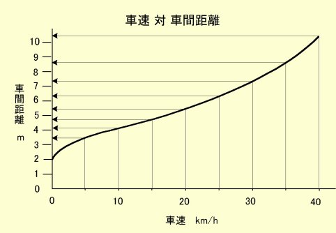
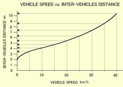
さらに、車体の運動エネルギは車速の2乗に比例することから、車速が0に近付くに連れて車体の運動エネルギは加速度的に減少し、ブレーキによる車間距離制御の効きや精度は加速度的に向上するので、車速が0に近付くに連れて車間距離は加速度的に縮小されても安全であり、一方、車速が徐行車速域を越えて増大するに連れて、車速の2乗に比例して増大する車体の運動エネルギによってブレーキによる車間距離制御の効きや精度は加速度的に低下するので、安全な車間距離は加速度的により大きく見積もられるべきことを考慮すれば、車速に応じた車間距離は、下図に例示する如く、車速0近傍の最徐行車速域では上に凸の曲線を描き、徐行車速以上の車速域では下に凸の曲線を描く勾配曲線に沿うべきものと考えられます。
しかし、車間距離は、単に自車の車速のみに依存するのではなく、先行車の車速と自車の車速の間の相対関係に応じて変化するので、車間距離の制御には先行車の車速に対する気配りを要し、渋滞時における如く先行車が発進、加速、減速、停止を繰り返すとき、先行車に対する車間距離を自車の車速の変化に応じた上記の如き最適値に調整するアクセルペダルやブレーキペダルの操作は、甚だ厄介で疲れる作業です。さりとて、安全のため不用意に車間距離を開け過ぎれば、渋滞車列を長大化させて渋滞を更に悪化させ、逆に車間距離が詰まり過ぎれば、追突の危険が忍び寄ります。
そこで、渋滞時には、随時アクセルおよびブレーキの操作をコンピュータ制御に任せ、車間距離を、常時、上図に例示するごとく、車速の増減に応じて増減する最適値としつつ、先行車の発進、加速、減速、停止に自動的に追従して自車を発進、加速、減速、停止させる渋滞時車輌走行制御装置を提案します。これによって渋滞時の運転操作はステアリングの微調整のみとなり、運転疲れが大幅に緩和されるだけでなく、発進や追従の遅れをなくし、渋滞そのものも大きく緩和されると思われます。
制御の要点は、上図の如き好ましい「車速対車間距離」に対応する下図のような「車間距離vs.目標車速マップ」を自車のコンピュータ内に用意しておき、先行車との車間距離をレーダー等にて実測しつつ、時々刻々の車間距離に応じて、コンピュータにより、ただひたすら、自車の車速を時々刻々の車間距離に対応する目標車速に制御することです。この制御は、「車間距離」という唯一の測定パラメータの変化に応じて「自車速」という唯一の制御パラメータを制御するものです。このように車間距離の時々刻々の値に対し自車速の時々刻々の値が車間距離に対応する目標車速に制御されれば、先行車の車速の変化は時々刻々の各瞬間の間に生ずる車間距離の変化を通して自車に対する先行車の相対速度の変化として把握されるので、車間距離を制御する制御であっても、先行車の車速の測定や推定は不要であり、車輌間通信を要せずして先行車の車速の変化に対処する協調型車間距離制御(CACC)を行うことができます。

今、簡単のため自車の前を走る先行車が、例えば、15km/hで定速走行しているとします。このとき、もしこの先行車に追走する自車の車間距離が、上のマップで見て車速15km/hに対応する車間距離4.76mよりも大きければ、そのような車間距離に対する自車の目標車速は15km/hより大きいので、自車は15km/h以上にて運転され、自車が先行車より速く走ることにより、車間距離は4.76mに至るまで縮まります。一方、もし車間距離が4.76mより小さければ、そのような車間距離に対する目標車速は15km/hより小さいので、自車は15km/h以下にて運転され、自車が先行車より遅く走ることにより、車間距離は4.76mに至るまで広がります。いずれにしても、こうして自車は15km/hにて走行する先行車に対し4.76mの車間距離をとって15km/hにて追走するようになります。同じことは、先行車が任意の他の車速にて定速走行する場合にも起こります。従って、先行車に対する自車の車間距離に応じて自車の車速を上のマップに例示するような車間距離に対応する目標車速に制御するようにしておけば、先行車が任意の車速にて定速走行するとき、それに合わせて当該車速に応じた最適車間距離を保って自車を先行車に追走させることができます。
また、例えば15km/hで定速走行している先行車に4.76mの車間距離を保って自車が追走している状態から、先行車が加速を開始すると、車間距離は4.76m以上に拡大するので、自車の車速も15km/h以上に加速され、先行車の加速が20km/hに落ち着けば、自車の車速も20km/hに落ち着き、以後自車は4.76mより拡大された20km/hに対応する車間距離(上のマップでは5.44m)を保って先行車に追走します。同様に、15km/hで定速走行している先行車に4.76mの車間距離を保って自車が追走している状態から、先行車が減速を開始すると、車間距離は4.76m以下に縮小するので、自車の車速も15km/h以下に減速され、先行車の減速が10km/hに落ち着けば、自車の車速も10km/hに落ち着き、以後自車は4.76mより縮小された10km/hに対応する車間距離(上のマップでは4.14m)を保って先行車に追走します。
そして先行車が停止すれば、上のマップでは2mの車間距離をとって、自車も停止します。その後、先行車が発進すれば、車間距離の増大に応じて自車も発進し、先行車の加速に伴い、その車速に対応する最適車間距離を取りつつ自車も加速します。
コンピュータによるデジタル演算制御は、数十ミリセカンド程度の微小周期にて繰り返し実行できます。そこで、上記の要領による追従制御がそのうような微小周期にて繰り返し行われるようにしておけば、先行車が発進し、加速し、減速し、停止することに追従して、数十ミリセカンドの微小周期にて繰り返し行われる追従制御により、常時車間距離を車速に対応した適正値に保ちつつ自車を先行車に追従して発進させ、加速させ、減速させ、停止させることができ、渋滞時の如く発進、加速、減速、停止を繰り返す場合にも、先行車の動きに自車を遅れなく且つ常時車速の増減に応じて適正に増減する車間距離を保って追走させることができます。
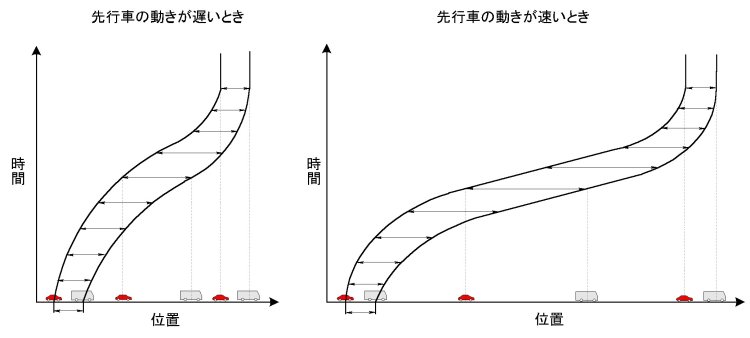
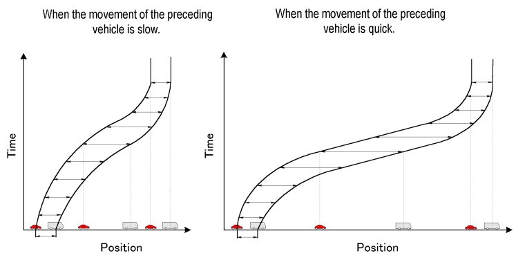
かかる制御により、先行車の発進、加速、減速、停止に追従して、自車は下図のように発進、加速、減速、停止します。先行車が停止状態から発進して緩やかに加速し、次いで緩やかに減速して停止するときには、左図のように、自車は先行車に対し小さな値までしか増大しない車間距離を取りつつ緩やかな動きで追走します。一方、先行車が停止状態から発進して急速に加速し、次いで急速に減速して停止するときには、右図のように、自車は先行車に対し大きな値まで増大する車間距離を取って敏速な動きで追走します。
この技術に自動操舵の技術を組み合わせれば、従走車は無人運転であって車速の増減に応じて車列が伸縮する車輌隊列運転も可能となります。
上記の数十ミリセカンドの周期にて繰り返される周期的追従制御の各周期に於いては、先行車に対する時々刻々の車間距離に対応する時々刻々の目標車速が上記マップを参照して算出され、時々刻々の自車車速を時々刻々の目標車速に一致させる制御が行われます。
この提案においては、一連の周期制御の当初に先ず目標車速Vtと実車速Vの大小関係が判断され、"Vt>V"ならば、追従制御は原動機の出力制御から開始され、原動機出力値Pが0に帰するまで追従制御は原動機出力制御に専念して行われ、他方、"Vt<V"ならば、追従制御はブレーキの制動力制御から開始され、ブレーキ制動力値Bが0に帰するまで追従制御はブレーキ制動力制御に専念して行われます。これは、通常のアクセルペダルおよびブレーキペダルによる手動運転においても、原動機出力を制御すべく右足を一度アクセルペダルに掛けたら、アクセルペダルの踏込みを零に戻すまでは、走行制御は右足によるアクセルペダルのみの操作により行われ、またブレーキ制動力を制御すべく右足を一度ブレーキペダルに掛けたら、ブレーキペダルの踏込みを零に戻すまでは、走行制御は右足によるブレーキペダルのみの操作により行われることと同じです。(偶に、アクセルペダルは右足で踏み、ブレーキペダルは左足で踏む運転者に遭遇しますが、これは、迅速なアクセル/ブレーキ間のペダル踏み替えを可能にする反面、両者が重なるとブレーキの無用な摩耗と燃料の無用な消費をもたらす運転方法であり、推奨されません。)
運転者により随意にオンオフされる自動追従制御がオフ状態からオンとされたとき、および "Vt>V"との判断により開始された原動機出力の周期的繰返し制御により原動機出力値Pが0に帰したとき、または"Vt<V"との判断により開始されたブレーキ制動力の周期的繰返し制御によりブレーキ制動力値Bが0に帰したとき、の次の瞬間が、上記の一連の周期制御の当初です。
一連の周期制御の当初の目標車速Vtと実車速Vの大小関係の判断の結果、"Vt>V"でもなく"Vt<V"でもないと判断されたとき、即ち"Vt=V"のときには、原動機出力値の変更もブレーキ制動力値の変更も要しないわけですが、ただ、それがVt=V=0によるものであるとき、即ち自車が停止中(先行車も停止中)であるときには、ブレーキ制動力値Bが一時停止時用の値Boとされます。
時々刻々のVを時々刻々のVtに一致させることを追及する原動機出力制御は、周期制御の各周期に於いて、その時点の原動機出力値Pを下記の各差分ΔP1,
ΔP2, ΔP3により修正することにより行われます。
ΔP1は、その時点のVtとVの差Vt-Vに基づき、下記の「Fp1マップ」に示されている如く変化する関数値
ΔP1=Fp1(Vt-V)
ΔP2は、その時点の目標車速VtであるVt(n)と一つ前の周期に於ける目標車速VtであったVt(n-1)の差ΔVtと、その時点の実車速VであるV(n)と一つ前の周期に於ける実車速VであったV(n-1)の差ΔVとの差ΔVt-ΔVに基づき下記の「Fp2マップ」に示されている如く変化する関数値
ΔP2=Fp2(ΔVt-ΔV)
ΔP3は、その時点の実車速VであるV(n)と一つ前の周期に於ける実車速VであったV(n-1)の差ΔVに基づき下記の「Fp3マップ」に示されている如く変化する関数値
ΔP3=Fp3(ΔV)
です。
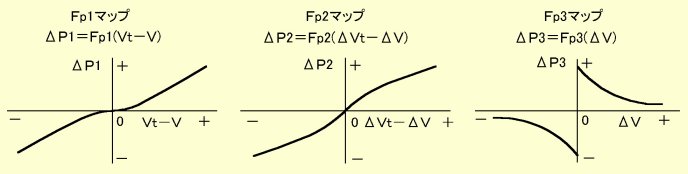
ΔP1は、目標車速Vtとそれに追従すべき実車速Vの偏差に基づき、それが正の値であるときには、それが大きい程、原動機出力をより大幅に増大させ、それが負の値であるときには、その絶対値が大きい程、原動機出力をより大幅に低減する制御量であり、VtとVの差を無くすためのフィードバック制御量です。
ΔP2は、目標車速Vtの変化速度とそれに追従すべき実車速Vの変化速度の比較から、目標車速の変化に対する実車速の変化が遅れ気味であるか進み気味であるかを判断し、目標車速の変化速度ΔVtが実車速の変化速度ΔVより大きく、目標車速の変化に対する実車速の変化が遅れ気味であれば、原動機出力を上げ、逆に目標車速の変化に対する実車速の変化が進み気味であれば、原動機出力を下げようとするものであり、VtとVの差を無くすためのフィードフォワード制御量です。
ΔP3は、各周期毎に偏差Vt-VおよびΔVt-ΔVに基づいて上記の如く原動機出力が修正されても、車体全体の重量が増せば車輌慣性の増大により実車速Vは変化しにくくなることに対する補正であり、搭乗人員および積載物による車輌慣性の変化を制御に反映させる制御量です。
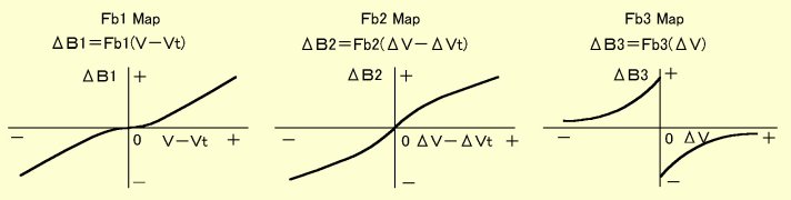
同様に、時々刻々のVを時々刻々のVtに一致させることを追及するブレーキ制動力制御は、周期制御の各周期に於いて、その時点のブレーキ制動力値Bを下記の各差分ΔB1,
ΔB2, ΔB3により修正することにより行われます。
ΔB1は、その時点のVとVtの差V-Vtに基づき、下記の「Fb1マップ」に示されている如く変化する関数値
ΔB1=Fb1(V-Vt)
ΔB2は、その時点の実車速VであるV(n)と一つ前の周期に於ける実車速VであったV(n-1)の差ΔVと、その時点の目標車速VtであるVt(n)と一つ前の周期に於ける目標車速VtであったVt(n-1)の差ΔVtとの差ΔV-ΔVtに基づき下記の「Fb2マップ」に示されている如く変化する関数値
ΔB2=Fb2(ΔV-ΔVt)
ΔB3は、その時点の実車速VであるV(n)と一つ前の周期に於ける実車速VであったV(n-1)の差ΔVに基づき下記の「Fb3マップ」に示されている如く変化する関数値
ΔB3=Fb3(ΔV)
です。
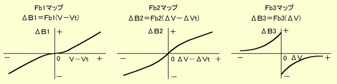
ΔB1, ΔB2, ΔB3が意味するところは、ΔP1, ΔP2, ΔP3について上に記した通り、VtとVの差を無くすためのフィードバック制御、フィードフォワード制御、車輌慣性の変化を反映させる制御です。
上記の通り、"Vt>V"ならば、追従制御は原動機の出力制御から開始し、原動機出力値Pが0に帰するまで制御は原動機出力制御に専念し、"Vt<V"ならば、追従制御はブレーキの制動力制御から開始し、ブレーキ制動力値Bが0に帰するまで制御はブレーキ制動力制御に専念することを、上記のΔP1,
ΔP2, ΔP3とΔB1, ΔB2, ΔB3に基づいて行う制御フローは以下のようになります。
運転者により渋滞追従制御が随意にオンとされたとき(スタート)、ステップ10にてその時点の車間距離Dに基づいて目標車速Vtが算出され、ステップ20にてその時点における実車速Vと比較されます。以後は、一連の原動機出力制御により原動機出力Pが0に帰したとき、または一連のブレーキ制動力制御によりブレーキ制動力Bが0に帰したとき、制御はステップ10へ戻り、ステップ20にて改めてVtとVが比較されます。
制御がステップ30へ進み、原動機出力制御が一旦開始された後は、制御はステップ30よりステップ40、50、60、70を巡り、原動機出力Pの値をFp1(Vt-V)+Fp2(ΔVt-ΔV)+Fp3(ΔV)により修正し、ステップ80にてPが0に帰したか否かを判断し、Pが0に帰するまではステップ30~70を繰り返します。これが、"Vt>V"の判断に基づいて行われる原動機出力制御に専念する制御です。
同様に、制御がステップ110へ進み、ブレーキ制動力制御が一旦開始された後は、制御はステップ120、130、140、150を巡り、ブレーキ制動力Bの値をFb1(V-Vt)+Fb2(ΔV-ΔVt)+Fb3(ΔV)により修正し、ステップ160にてBが0に帰したか否かを判断し、Bが0に帰するまではステップ110~150を繰り返します。これが、"V>Vt"の判断に基づいて行われるブレーキ制動力制御に専念する制御です。
PまたはBが0となり、制御がステップ10へ戻ったとき、"Vt>V"でも"V>Vt"でもなく、従って"Vt=V"であり、車輌が走行中であってVt=0ではなく、ステップ102の答がノーのときには、制御はステップ100、102を周ってステップ10へ還流しますが、このとき、原動機が内燃機関であれば、エンジンブレーキが作用します。このとき路面が下り坂にあり、エンジンブレーキがその下り勾配に適した強さであると、P=0、B=0(アクセルペダルもブレーキペダルも踏まれない状態に相当)のままで、制御はステップ10、20、100、102を周って循環します。この場合、渋滞追従制御中には、道路が下り勾配であるとき、勾配に応じて自動変速機をD~Lレンジ間に自動で切り換えるようにしておけば、下り坂でエンジンブレーキを追従制御に関連させて自動で最適状態に効かせることができます。
一方、PまたはBが0となり、制御がステップ10へ戻ったとき、"Vt>V"でなく、"V>Vt"でもなく、従って"Vt=V"であり、それが特に"Vt=V=0"であるときには、制御はステップ104へ進み、ブレーキ制動力値Bが一時停止時制動力Boに設定されます。
渋滞追従制御が開始されると、制御は数十ミリセカンドの微小周期にて以上の制御のいずれかを実行しつつ上の制御フローを巡って周回し、車輌の走行が上の「車間距離vs.目標車速マップ」に沿うよう、車輌の制駆動状態を逐次修正します。
車種毎の車輌の加速特性および制動特性に応じて「車間距離vs.目標車速マップ」、「Fp1マップ」、「Fp2マップ」、「Fp3マップ」、「Fb1マップ」、「Fb2マップ」、「Fb3マップ」をより適切に設定すべく、車輌の試験走行を通してマップを逐次修正することにより、追従走行性能の向上を限りなく追及することができます。
尚、車間距離および車速の測定には、その測定手段の精度に基いて実測値に誤差が伴ないますが、このことは上の制御にとって問題とはなりません。例えば、先行車が正確に15km/hにて定速走行しているとき、それに同速にて追走する自車の車速測定手段が測定値を5%高く測定するとすると、車速は15.75km/hと測定されるので、それに対応すべき上のマップによる車間距離は4.82mとなります。このとき車間距離測定手段がこの程度の車間距離の測定においては測定値を7%小さく測定する誤差を伴うものであるとすると、4.82mは実際には5.16mの測定値となるので、結局このとき自車は正確に15km/hにて定速走行する先行車に5.16mの車間距離をとって定速にて追走することになります。
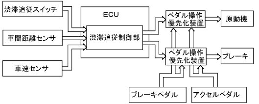
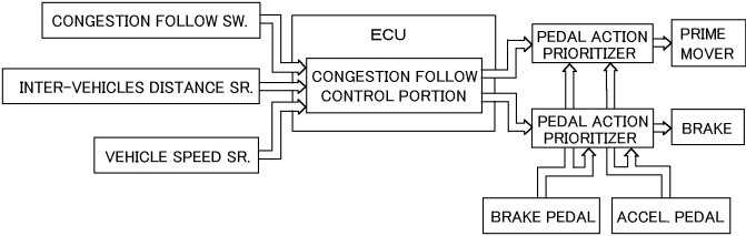
上記のフローチャートを巡る演算は、この渋滞時車輌走行制御装置がオンとされている間、絶え間なく続けられてよく、アクセルペダルもブレーキペダルも踏まれていない限り、原動機またはブレーキは演算結果に従って作動されればよいのです。そして、下図のようなアクセル/ブレーキ作動システムにより、アクセルペダルまたはブレーキペダルが踏まれたときには、その間だけ原動機またはブレーキの作動をアクセルペダルまたはブレーキペダルの操作に任せ、アクセルペダルまたはブレーキペダルの踏込みがなされなくなったときには、原動機またはブレーキの作動をアクセルペダルまたはブレーキペダルの踏込み中にも継続して維持されている制御演算に基づく作動に戻せばよいのです。
【特許請求の範囲】
【請求項1】
渋滞走行時に先行車の進行に追従して自車を進行させるよう車輌の原動機とブレーキを制御する渋滞時車輌走行制御装置にして、先行車および自車が共に停止しているときの最小車間距離より先行車に対する自車の車間距離が増大するに連れて自車の車速を0より始まって次第に増大させるよう車間距離に対応して目標車速を予め定めたマップを用意しておき、車間距離の実測値に基づいて実車速を前記マップ上の該車間距離に対応する目標車速に近づけるよう前記原動機の出力または前記ブレーキの制動力を制御するようになっており、
実車速を目標車速に近づける制御に於いては、目標車速が実車速より大きいか否かが判断され、目標車速が実車速より大きいと判断されたときには、実車速を目標車速に近づける制御は原動機出力の制御から始められ、目標車速が実車速より小さいと判断されたときには、実車速を目標車速に近づける制御は制動力の制御から始められるようになっており、
目標車速が実車速より大きいと判断されて実車速を目標車速に近づける制御が原動機出力の制御から始められるときには、制動力が一度0とされ、目標車速が実車速より大きくもなく小さくもないと判断されたときには、目標車速または実車速が0であるか否かが判断され、目標車速または実車速が0であると判断されたときには、制動力が所定の停車時制動力に設定されるようになっていることを特徴とする渋滞時車輌走行制御装置。
【請求項2】
渋滞走行時に先行車の進行に追従して自車を進行させるよう車輌の原動機とブレーキを制御する渋滞時車輌走行制御装置にして、先行車および自車が共に停止しているときの最小車間距離より先行車に対する自車の車間距離が増大するに連れて自車の車速を0より始まって次第に増大させるよう車間距離に対応して目標車速を予め定めたマップを用意しておき、車間距離の実測値に基づいて実車速を前記マップ上の該車間距離に対応する目標車速に近づけるよう前記原動機の出力または前記ブレーキの制動力を制御するようになっており、
原動機出力の制御により実車速を目標車速に近づける制御は、微小サイクルタイム毎に繰り返される制御サイクルの各サイクルに於ける原動機出力を、該サイクルに於ける目標車速と実車速の差に基づく第一の原動機出力変更値と、該サイクルに於ける目標車速と前回のサイクルに於ける目標車速の差と該サイクルに於ける実車速と前回のサイクルに於ける実車速の差の差に基づく第二の原動機出力変更値と、該サイクルに於ける実車速と前回のサイクルに於ける実車速の差に基づく第三の原動機出力変更値の和により修正する制御であることを特徴とする渋滞時車輌走行制御装置。
【請求項3】
渋滞走行時に先行車の進行に追従して自車を進行させるよう車輌の原動機とブレーキを制御する渋滞時車輌走行制御装置にして、先行車および自車が共に停止しているときの最小車間距離より先行車に対する自車の車間距離が増大するに連れて自車の車速を0より始まって次第に増大させるよう車間距離に対応して目標車速を予め定めたマップを用意しておき、車間距離の実測値に基づいて実車速を前記マップ上の該車間距離に対応する目標車速に近づけるよう前記原動機の出力または前記ブレーキの制動力を制御するようになっており、
制動力の制御により実車速を目標車速に近づける制御は、微小サイクルタイム毎に繰り返される制御サイクルの各サイクルに於ける制動力を、該サイクルに於ける実車速と目標車速の差に基づく第一の制動力変更値と、該サイクルに於ける実車速と前回のサイクルに於ける実車速の差と該サイクルに於ける目標車速と前回のサイクルに於ける目標車速の差の差に基づく第二の制動力変更値と、該サイクルに於ける実車速と前回のサイクルに於ける実車速の差に基づく第三の制動力変更値の和により修正する制御であることを特徴とする渋滞時車輌走行制御装置。
【請求項4】
実車速を目標車速に近づける制御は、運転者によりオンとオフの間に切り換えられる渋滞追従スイッチがオンとされることにより実行され、該渋滞追従スイッチがオンとされているときアクセルペダルとブレーキペダルのいずれかが踏み込まれたときには、アクセルペダルまたはブレーキペダルによる原動機またはブレーキの制御を優先させるべく、実車速を目標車速に近づける原動機出力または制動力の制御値の算出は継続されるが算出された制御値による原動機またはブレーキの制御は中断されるようになっていることを特徴とする請求項1~3のいずれかに記載の渋滞時車輌走行制御装置。
【請求項5】
実車速を目標車速に近づける制御は、原動機出力の制御として開始されたときには、原動機出力が下限値に達するまでは、目標車速と実車速の間の大小関係の如何に拘わらず原動機出力の制御として行われ、原動機出力が下限値に達したとき、目標車速と実車速の間の大小関係の判定が再度行われ、また制動力の制御として開始されたときには、制動力が下限値に達するまでは、目標車速と実車速の間の大小関係の如何に拘わらず制動力の制御として行われ、制動力が下限値に達したとき、目標車速と実車速の間の大小関係の判定が再度行われ、再度の目標車速と実車速の間の大小関係の判定以降は、目標車速が実車速より大きいと判断されたときには、実車速を目標車速に近づける制御は原動機出力の制御として再開され、目標車速が実車速より小さいと判断されたときには、実車速を目標車速に近づける制御は制動力の制御として再開されるようになっていることを特徴とする請求項1~4のいずれかに記載の渋滞時車輌走行制御装置。
Topへ戻る
惰性走行を生かしたエコ運転ができる車輌
現在のオートマチック車を平地で運転するとき、多くの人は、シフトレバーをD位置にセットしたDレンジのままで、アクセルペダルとブレーキペダルを踏み替え操作し、発進、加速、減速、一時停止を行っていると思われます。オートマチック車では、エンジンと変速機の間に流体式トルクコンバータが介装されているので、変速機の入口に組み込まれたクラッチを連結状態にしてエンジンにより車輪を駆動する態勢であるDレンジのままブレーキペダルを踏んで車輌を停止させても、流体式トルクコンバータの滑り回転により、エンジンはエンスト(engine
stall, engine stop)を起こすことなく回転状態に維持されるようになっています。このように車輌の駆動系に流体式トルクコンバータが組み込まれていることと、変速機の変速比が車輌の走行状態に応じて自動的に切り替えられるようになったことにより、平地での自動車の運転は、シフトレバーをD位置にセットしておけば、後はアクセルペダルとブレーキペダルを踏み替え操作するだけで、発進、加速、減速、一時停止が自由にできるようになりました。
車輪の回転速度は車速に応じて変化し、車速が大きい程、車輪は速く回転します。エンジンの回転速度はアクセルペダルの踏込み度合に応じて変化し、アクセルペダルの踏込みが深くなる程、エンジンの回転速度は増大します。従って、エンジンが車輪に駆動連結されたDレンジで車輌が運転されていると、車輌は、車速とアクセルペダル踏込み度合の間の相対的大小関係に応じて、エンジンにより車輪が駆動される状態か、逆に車輪によりエンジンが駆動される状態か、これらの中間にあって、車速が丁度エンジンの回転速度に対応し、エンジンと車輪の間でどちらがどちらより駆動されることもない状態があります。
シフトレバーがD位置、2位置、L位置のような走行レンジ位置にシフトされていて、アクセルペダルがある程度以上に踏み込まれると、エンジンにより車輪が駆動され、車輌は通常の駆動走行状態となります。
アクセルペダルが解放されると、 エンジンへの燃料の供給はエンジンを運転状態に維持するに必要な最低限度に絞られ、エンジンはごく低速のアイドル回転数で回転しようとしますが、 シフトレバーがD位置、2位置、L位置のような走行レンジ位置にシフトされていて、車輌がある程度以上の速度で走行していると、車体の走行慣性により、上記の流体式トルクコンバータが設けられていても、エンジンが車輪の側からアイドル回転数以上に駆動されることになります。この状態では、エンジンは車輌の慣性走行を抑制するよう作用し、ブレーキペダルが解放されていても、車輌は制動されます。これが「エンジンブレーキ」と称されるものであり、これはこれで車輌運転の安定性の観点から有意義な作用であり、またエンジンブレーキは下り坂でのブレーキの過熱防止には必須の作用ですが、車輌の平地での惰性走行距離は、車輌がそのようなエンジンブレーキの作用なしで惰性走行する距離より短くなります。
ところで、車輌の運転中には、車輌を惰性走行させればよい場合が多々あります。例えば、前方に見えてきた信号が赤だったり、青から赤に変わったばかりで、その先一時停止を強いられることは確実であり、信号の手前まで急ぐことなくゆっくりと到達できればよいときがあります。このようなときには、なるべくブレーキを踏まないで所要の位置に停車するよう、早めにアクセルペダルを解放し、車輌を慣性走行させることにより、燃料を節約できますが、この場合、更に、惰性走行中にエンジンブレーキが作用しないようにすれば、それだけ惰性走行距離を伸ばせるので、その分、より早めにアクセルペダルを解放し、燃料をより一層節約できます。また、ごく緩やかな下り坂での定速走行の如く、エンジンブレーキなしで、車輌の慣性を最大限に生かした走行を行い、燃料を節約できる場面もあります。その他、車輌の運転中には、特にそれ以上加速しなくてもよく、或いは車速が多少落ちても差し支えなく、アクセルペダルを踏みたくはないが、かといってアクセルペダルを放してしまうと、エンジンブレーキが作用して車速が落ち過ぎ、それでは困るという、エンジン駆動もなくまたエンジンブレーキも作用しない走行が望まれる場面もあります。
そこでそのようなエンジンブレーキなしの惰性走行が望まれ或いは許される場合には容易にそうさせることができるようになっていれば、車輌の運行において車輌の走行慣性を最大限に生かすことができ、車体がより頑丈に作られることによってより重くなり、加速に要する燃料量が増大しても、その増大分の燃料のエネルギは車輌の慣性エネルギの増大として蓄えられ、空気および路面からの抵抗に抗して車輌を慣性走行させる距離の増大として回収されるので、燃費を悪化させることなく車体の強度を上げ、衝突事故に対してより安全な車輌をつくることができます。車体の強度が衝突事故における人体の損傷に如何に大きく影響するかは、身を護るために敢てベンツを選ぶ人がいるように、知る人ぞ知るところです。
変速機の入口には、冒頭に記した通り、エンジンとの連結を断続するクラッチ が設けられており、この変速機入口クラッチは、シフトレバーがN位置にセットされれば解除されるので、惰性走行中にエンジンブレーキを作用させたくなければ、シフトレバーをその都度N位置に切り替え、変速機入口クラッチを解除すればよいのです。しかし、それは面倒であり、またそれでは、シフトレバーをD位置にセットしておけばアクセルペダルとブレーキペダルの操作のみで車輌の発進から加速、減速、一時停止に至るあらゆる走行状態を達成できるというオートマチック車の利点を削ぐことになります。
そこで提案したいのが、シフトレバーの操作を要せず、アクセルペダルの僅かな操作によりエンジンブレーキを解除できるようにすることです。
オートマチック車には、下図よりソレノイド弁30を無くし、油圧源からの油路38をポート18に直に接続した構造の変速駆動機構が組み込まれています。換言すれば、本提案は、既存の変速駆動機構にソレノイド弁30を追加し、このソレノイド弁30を、車速が徐行車速以上であるときのみ、アクセルペダル48の戻り終端位置からの微小踏込みδに応動させることによりエンジンブレーキを解除することです。
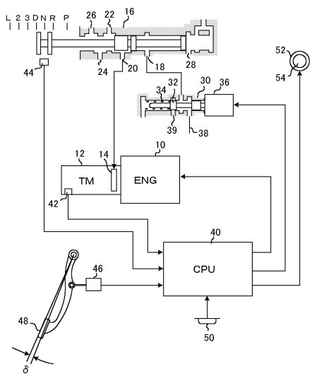
オートマチック車においては、車輪は、上の概略図に示すように、エンジン10より、入口部にクラッチ14を含む変速機12を介して駆動されるようになっています。尚、上図には示されていませんが、エンジン10と変速機12の間には流体式トルクコンバータが組み込まれており、車輌がDレンジのまま(即ちクラッチ14が係合したまま)ブレーキペダルの踏込みにより停車しても、トルクコンバータの滑り回転によりエンジンはアイドル回転を続けられるようになっています。
変速機12内には変速比をいくつかの値の間に切り替える変速歯車機構が組み込まれており、変速制御弁16がD~L位置にセットされたときには、油圧入口ポート18に供給された油圧が油圧出口ポート20に伝わることによりクラッチ14が係合され、エンジン10より上記の流体式トルクコンバータを経て入力される回転が車速とアクセルペダル踏込み量の間の相対関係に応じて自動的に変速され、変速機は低速段から高速段までの適当な変速段を達成するようになっています。そして更に変速制御弁16が3位置、2位置、L位置へとシフトされると、油圧出口ポート22、24、26に順に追加して現れる油圧により、変速機は、3速段、2速段、1速段へ強制的にシフトダウンされるようになっています。
現在、オートマチック車においては、油圧入口ポート18には、油路38より油圧が直接供給されています。変速制御弁16が図示の如くN位置にセットされていれば、油圧入口ポート18に供給された油圧は油圧出口ポート20へは伝わらず、クラッチ14は解除されています。そして、変速制御弁16がD~L位置にシフトされると、クラッチ14に油圧が供給され、クラッチが係合されるようになっています。
そこで、油路38から油圧入口ポート18に至る油路の途中にソレノイド36にて駆動される切替弁30を設けておき、常時は切替弁30は図示の状態にあって油路38は油圧入口ポート18に連通しているが、車輌がDレンジにて徐行車速以上の所定車速以上で走行しているときに限り、アクセルペダルが戻り位置ではなく、それより微小量δだけ踏まれたときには、それをセンサ46で感知し、電子制御装置40を介してソレノイド36を励磁し、切替弁30を図にて左方へ切り替え、油圧入口ポート18を油路38から遮断して排油ポート39に通じさせるようにしておけば、前方に見えてきた信号が赤だったり、青から赤に変わったばかりで、その先一時停止を強いられることは確実であり、信号の手前まで急ぐことなくゆっくりと到達できればよいときとか、ごく緩やかな下り坂での定速走行の如く、エンジンブレーキなしで、車輌の慣性を最大限に生かして走行したいときとか、特にそれ以上加速しなくてもよく、或いは車速が多少落ちても差し支えなく、エンジン駆動もなくまたエンジンブレーキも作用しない走行が望まれるとき、シフトレバーをN位置に切り替えなくても、アクセルペダルを微かに踏み込むだけでクラッチ14を解除し、エンジンブレーキが掛からない惰性走行にすることができます。
制御の流れは以下のようになります。
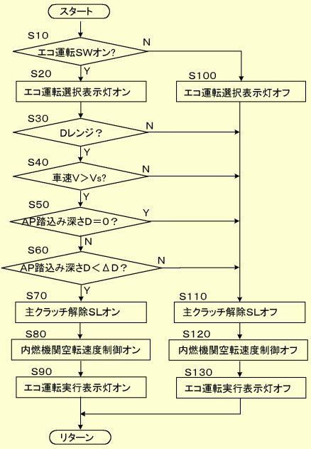
上記の微小踏込み量δ(<ΔD)は、運転者がアクセルペダルを戻り終端位置よりは確かに踏み込んだと明確に認識できる範囲の踏込み深さであるが、空気抵抗やタイヤの変形抵抗を相殺して車輌を徐行車速以上の速度にて定速走行させるアクセルペダル踏込み深さより小さい値とされます。
以上の作動をまとめると、以下の通りとなります。
(1)アクセルペダルが戻り終端位置まで戻されたときには、従来通りDレンジでのエンジンブレーキが作用するので、アクセルペダルの解放によりエンジンブレーキが作用するという従来通りの運転感覚を確保することができる。
(2)車輌を停止状態から発進させるときには、車輌の全質量をそれに作用する大きな慣性に抗して動かす必要があることから、アクセルペダルは通常戻り終端位置から或る程度の大きさの踏込み深さまで一気に踏み込まれるので、車輌の発進時にアクセルペダルが上記δの踏込み深さを通過するのは車輌がまだ徐行車速内にあるときであり、主クラッチが解除されるのは車速が徐行車速以上であるときに限られるので、車輌の発進時にアクセルペダルが戻り終端位置から踏み込まれる過程で主クラッチが解除されることはなく、車輌の発進時にアクセルペダルの踏込みに対する車輌の加速に息つきのような違和感を生ずることは起こらない。
(3)主クラッチが解除されるのは車速が徐行車速以上であるときに限られるので、車庫入れ時等に車輌を徐行させるべく軽く踏んだアクセルペダルの踏込み深さが上記δとなっても、主クラッチが解除されて車輪が駆動されなくなるようなことは起こらない。
(4)車輌には走行による空気抵抗やタイヤの変形抵抗が作用し、車輌を徐行車速以上の速度にて定速走行させるには、アクセルペダルはそのような空気抵抗やタイヤの変形抵抗を相殺するに足る或る程度の大きさの踏込み深さ以上に踏み込まれる。従って、上記δが空気抵抗やタイヤの変形抵抗を相殺して車輌を徐行車速以上の速度にて定速走行させるアクセルペダル踏込み深さより小さい範囲に設定されていれば、車輌の徐行車速以上での定速走行時に主クラッチが解除されることはない。
(5)車輌が徐行車速以上に立ち上がった後、車速が空気抵抗やタイヤの変形抵抗により多少落ちても差し支えなく、エンジンブレーキを効かせる必要もなく、車輌を慣性によりできるだけ長く走行させたいとき、シフトレバーをN位置に切り換えなくても、アクセルペダルを極僅かに踏むことにより、自動変速機の主クラッチを解除し、エンジンブレーキを作用させないようにして、車輌の慣性走行能力を最大限に発揮させることができる。
尚、そのようにアクセルペダルの微小踏込みでクラッチが遮断されるのは、当機能を求めて運転者が手動のエコ運転スイッチ50をオンにしているときだけとしてよいのです。
【特許請求の範囲】
【請求項1】
内燃機関により自動変速機を介して車輪が駆動される車輌にして、前記自動変速機はそれがDレンジに設定されたとき係合されるクラッチであって解除されると前記内燃機関と前記車輪の間の前進駆動連結が解除される主クラッチを含んでおり、前記自動変速機がDレンジに設定されており、車速が徐行車速以上であって、アクセルペダルが戻り終端位置よりは確かに踏み込んだと運転者が明確に認識できる範囲の踏込み深さであるが空気抵抗やタイヤの変形抵抗を相殺して車輌を徐行車速以上の速度にて定速走行させるアクセルペダル踏込み深さより小さい所定の微小踏込み深さ以内の範囲で踏み込まれているとき前記主クラッチが解除されるようになっていることを特徴とする車輌。
【請求項2】
前記自動変速機がDレンジに設定されており、車速が徐行車速以上であって、アクセルペダルが戻り終端位置より前記所定の微小踏込み深さ以内の範囲で踏み込まれていることにより前記主クラッチが解除されたとき、前記内燃機関の空転速度を車速に応じて制御するようになっていることを特徴とする請求項1に記載の車輌。
【請求項3】
前記自動変速機がDレンジに設定されており、車速が徐行車速以上であって、アクセルペダルが戻り終端位置より前記所定の微小踏込み深さ以内の範囲で踏み込まれているとき前記主クラッチが解除されるのは、運転者により随意に操作されるエコ運転スイッチがオンとされているときに限られることを特徴とする請求項1または2に記載の車輌。
【請求項4】
前記エコ運転スイッチがオンとされていることを運転者に示すエコ運転選択表示灯が設けられていることを特徴とする請求項3に記載の車輌。
【請求項5】
前記自動変速機がDレンジに設定されており、車速が徐行車速以上であって、アクセルペダルが戻り終端位置より前記所定の微小踏込み深さ以内の範囲で踏み込まれていることにより前記主クラッチが解除されたことを運転者に示すエコ運転実行表示灯が設けられていることを特徴とする請求項1~4のいずれかに記載の車輌。
Topへ戻る
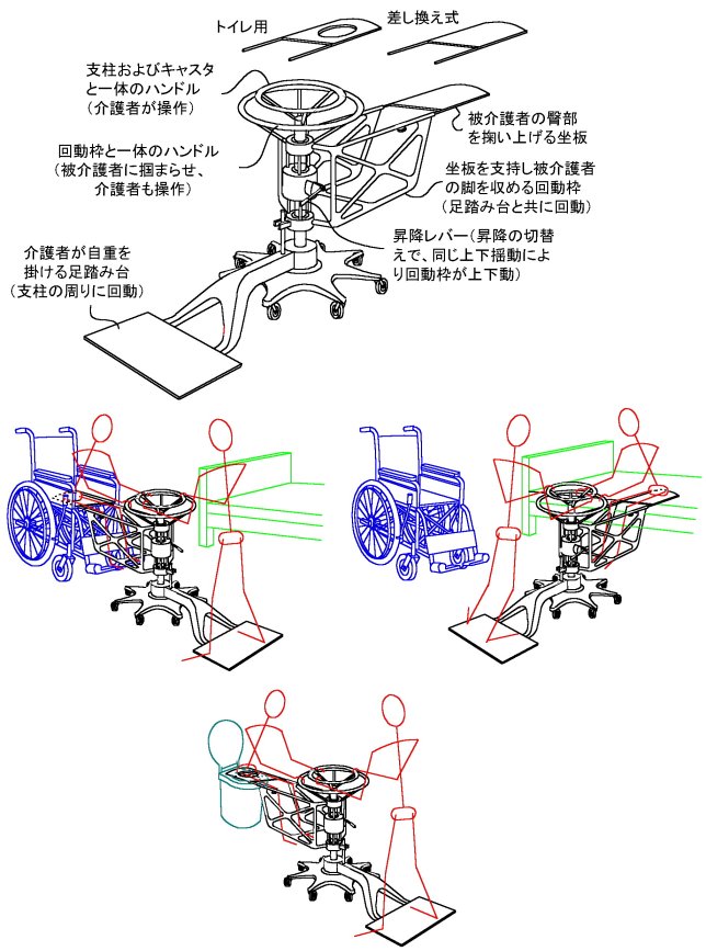
歩行困難な被介護者のための搬送装置
近時、移動には車椅子を要する被介護者が増えていますが、更に、要車椅子被介護者のなかには、ベッドから車椅子への移乗もまた車椅子からベッドへの帰還も、ご自身ではままならない方々が増えています。そのため、そのような方々をベッドと車椅子の間に抱きかかえて移し替える介護者の腰痛が新たな問題として浮上してきています。また介護における排泄の世話は、介護者にとって特に大きな負担となっています。
ここに提案する装置は、介護者が、腰を屈めたり、被介護者を抱きかかえたりすることなく、、被介護者を腰掛け姿勢のまま、介護者一人で、ベッドと車椅子の間に、楽々移し替えることができるだけでなく、被介護者を腰掛姿勢に掬い上げた状態でそのままトイレまで搬送し、お尻を様式トイレの便座の上に用足し姿勢に載置し、用足しさせ、用足し後はそのままトイレよりベッドまで搬送することができるものです。近時、様式トイレには、お尻洗浄噴水装置の装備が広く行きわたってきているので、こうして、足腰の動きが不自由な被介護者も、便器ではなく、トイレで、気持ち良く用足しをすることができ、また事後のお尻を噴水洗浄することにより、介護者は被介護者のお尻拭きから解放されます。
介護者は、被介護者を坐板の上に前向きに座らせ、足踏み台に片足を掛けて被介護者の体重を自重で釣り合わせ、他方の足で床を蹴って被介護者を搬送することができます。キャスタに適当な広がりを与えておけば、それによって装置にはかなりの程度の自立性が得られるので、坐板に掛かる被介護者の体重と足踏み台に掛かる介護者の体重の間にかなり大きな差があっても、装置が転倒する恐れのない設計とすることができます。尚、図示の構造には含まれていませんが、回動枠より下方へ向けて随時突き出せる支持脚を設けておけば、介護者は随時足踏み台より離れることができます。
【特許請求の範囲】
【請求項1】
複数個のキャスターにより床面上を任意の方向に自由に走行できる台座と、前記台座により垂直に支持された支柱と、前記支柱によりその周りに自由に回動可能に支持されて前記支柱の両側に延在する回動枠体とを有し、前記回動枠体の一方の側の延在端には被介護者を前記支柱に向かって座らせる坐板が取り付けられており、前記回動枠体の他方の側の延在端には介護者が足で踏んで自分の体重を掛ける足踏み台が設けられていることを特徴とする歩行困難な被介護者のための搬送装置。
【請求項2】
前記回動枠体は前記坐板を取り付ける端部に一対の水平な管状の腕部を有し、前記坐板はその前記回動枠体の腕部に近い側の両端部より前記回動枠体の管状腕部内に差込まれる一対の棒状支脚を有し、該一対の棒状支脚にて前記回動枠体の管状腕部に抜き差しされることにより前記回動枠体に対し着脱されるようになっていることを特徴とする請求項1に記載の搬送装置。
【請求項3】
前記坐板の上下両面の少なくとも一方には該坐板の表面を他の物体に対し接触させつつ滑らせるとき該坐板に対する該物体の相対的移動方向に湾曲傾斜して該物体に対する該坐板の滑り抵抗を減ずる立ち毛が植設されていることを特徴とする請求項1または2に記載の搬送装置。
【請求項4】
前記坐板は互に交換して前記回動枠体に取り付けられるよう複数個準備されていることを特徴とする請求項1、2または3に記載の搬送装置。
【請求項5】
前記複数個の坐板の少なくとも一つは中央部に洋式便座の内縁に整合する開口を有し、被介護者が該坐板上に着座したまま用便をすませることができるようになっていることを特徴とする請求項4に記載の搬送装置。
【請求項6】
前記回動枠体にはこれを前記支柱の周りに回動させるための環状ハンドルが設けられていることを特徴とする請求項1~5のいずれかに記載の搬送装置。
【請求項7】
前記支柱にはその中心軸線に同心の環状ハンドルが設けられていることを特徴とする請求項1~6のいずれかに記載の搬送装置。
【請求項8】
前記回動枠体を前記支柱の周りに自由に回動可能に支持すると共に前記支柱による前記回動枠体の支持の高さ位置を若干の寸法範囲内にて調節可能にするため、前記支柱に固定されたピストンと前記回動枠体に固定されたシリンダとによる油圧シリンダ/ピストン装置が設けられており、前記シリンダ内の前記ピストンにて仕切られた上部シリンダ室と下部シリンダ室の間に油を移送することにより前記高さ位置が調節されるようになっていることを特徴とする請求項1~7のいずれかに記載の搬送装置。
【請求項9】
前記シリンダ内の上部シリンダ室と下部シリンダ室の間に油を移送する手段として、扇形のポンプ室内にてポンプ板が扇の要の位置にある回動軸線の周りに往復揺動するポンプが設けられており、前記ポンプ板にはその一方の側から他方の側へのみ油の流れを許す第一の逆止弁およびこれとは逆に前記他方の側から前記一方の側へのみ油の流れを許す第二の逆止弁とが並列に設けられていると共に、前記第一の逆止弁を作動可能にすると同時に前記第二の逆止弁を遮断状態とする第一の切り換え位置と前記第二の逆止弁を作動可能にすると同時に前記第一の逆止弁を遮断状態とする第二の切り換え位置の間に切り換えられるポンプ作動方向切り換え手段が設けられていることを特徴とする請求項8に記載の搬送装置。
【請求項10】
前記ポンプ板は前記回動軸線の周りの往復揺動の少なくとも一つの位置にあるとき前記扇形のポンプ室を前記上部シリンダ室または前記下部シリンダ室へ通じるポートを閉じるようになっていることを特徴とする請求項8または9に記載の搬送装置。
Topへ戻る
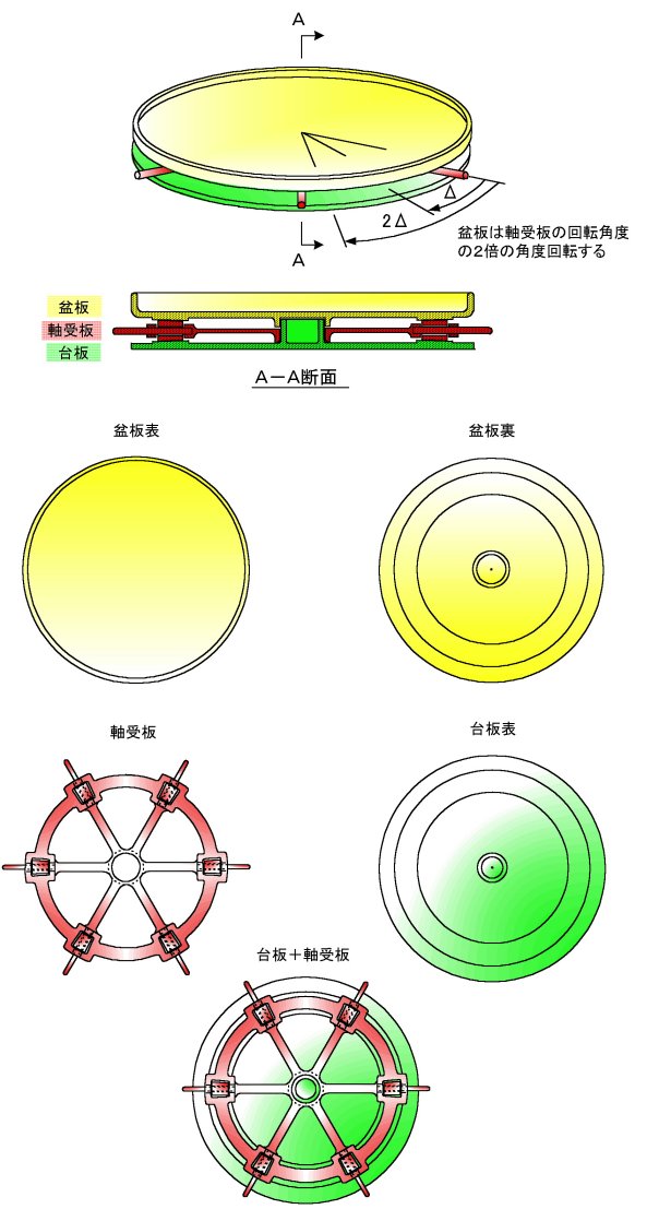
回転式配膳台
病院や老人ホームにて病人や高齢者に料理が盆に並べられた状態で供されると、手が届きにくい後方に位置する料理は残されがちとなります。もし盆が容易に回転できれば、食事に際して、随時意のままに盆を回転させ、食せんとする料理をその都度手前に引き寄せ、すべての料理を残りなく、またこぼれやすい料理も落ちこぼしなく、食するとこができます。
但し、盆は、回転式とされるにしても、以下のような条件を満たす必要があるでしょう。
(1)使用のたびに容易に且つ隅々まできれいに水洗できること。
(2)手に持って水洗でき、水洗時に手に大きな負担をかけない軽い構造であること。
(3)こぼれた食物により汚染されても回転機構に支障を来たしにくいこと。
(4)できるだけ小さい手の動きにより軽く大きく回転させることができ、それでいて回転位置は安定していること。
(5)安価に製造できること。
上記の諸条件を満たすべく、下図のような盆版、軸受板、台板を積み重ねた回転式配膳台を提案します。
【特許請求の範囲】
【請求項1】
台板と軸受板と盆板とが共通の回転中心軸線の周りに相互に回転可能に且つ該回転中心軸線に沿って互いに分離可能に回転係合した状態に積層され、前記軸受板は少なくとも3つのローラとこれらのローラを前記回転中心軸線より放射状に延在するローラ転動軸線の周りに転動可能に支持するローラ支持枠とを有しており、前記盆板が前記台板に対し前記回転中心軸線の周りに回転するとき前記ローラが前記台板の上面と前記盆板の下面とに接した状態で前記ローラ転動軸線の周りに転動するようになっており、前記ローラ支持枠は前記台板および前記盆板の外周縁の位置より突き出たハンドルを備え、前記ローラ支持枠が前記ハンドルにて前記台板に対し前記回転中心軸線の周りに回転されるとき、前記台板に対する前記ローラ支持枠の回転角度の2倍の角度だけ前記盆板が前記台板に対し回転されるようになっていることを特徴とする回転式配膳台。
【請求項2】
前記ローラは前記ローラ転動軸線に沿って前記回転中心軸線に近い側の内端と前記回転中心軸線より遠い側の外端との径が異なるテーパ付きローラであり、前記外端と前記内端の径の比が前記回転中心軸線に対する前記外端と前記内端の距離の比とされ、前記台板の上面および前記盆板の下面には前記ローラが当接する部分に前記テーパ付きローラのテーパ状周面の傾斜に適合する傾斜角の環状帯域が設けられていることを特徴とする請求項1に記載の回転式配膳台。
【請求項3】
前記ローラ支持枠は、それを前記台板に対し前記回転中心軸線の周りに回転可能に係合させる中心軸受部と、前記ローラを転動可能に支持する複数のローラ軸受部と、前記複数のローラ軸受部を互に連結する環状枠部と、前記複数のローラ軸受部の各々と前記中心軸受部とを連結する車輻状枠部とを有する構造体であることを特徴とする請求項1または2に記載の回転式配膳台。
【請求項4】
前記ハンドルは前記ローラを転動式に支持する軸の延長端であることを特徴とする請求項1~3のいずれかに記載の回転式配膳台。
Topへ戻る
水道蛇口水圧によりブラシを回動させる食器洗浄器
水道蛇口の水にはかなり高い水圧が掛かっています。この水圧は、水の流れの勢いによる動圧ではなく、流れが止まっていても作用する静水圧であり、水のチョロチョロ流しによっても仕事ができる貴重なエネルギ源です。食器洗いに水道蛇口より水を流出させるのであれば、ただ単に水を使用するだけで、そこに含まれる静水圧エネルギを利用しないのはまことにもったいないことです。そこで、水道蛇口からの水で食器を洗うときには、水流だけでなく、その静水圧エネルギを洗浄作業に役立てることができる食器洗浄器を提案します。
水道の蛇口を受け入れる蛇口受け口26にて水道の蛇口に取り付けられ、ねじ40にて固定されるように作られた装置は、その中心線C-Cを通る一つの縦断面で見て、下図左に示すように、円筒状のハウジング16と、その内部で中心線C-Cの回りを往復回動する回動ピストン10よりなっています。これより回動ピストン10を取り除いてハウジング16のみを示すと、下図右のようになります。
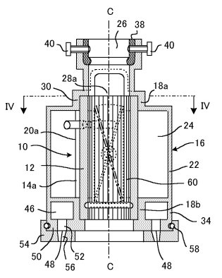
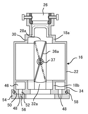
中心線C-Cの周りに上図右とは直角をなす断面でハウジング16を見ると下図のようになります。
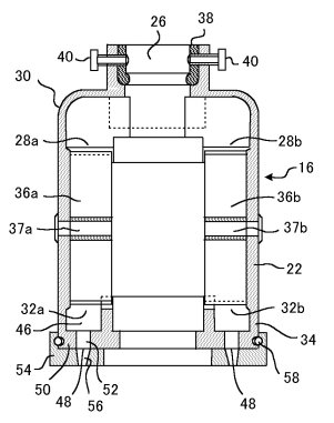
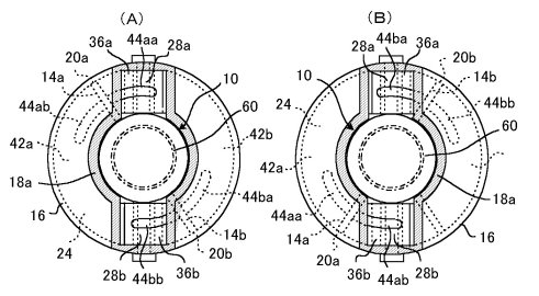
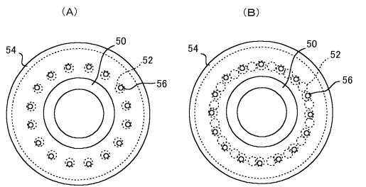
また最初に示した図にIV-IVで示す水平断面で装置を切って下向きに見ると、下図のように見えます。図(A)は、回動ピストン10が上から見て時計回りに回動して終端位置に来ている状態であり、図(B)は、回動ピストン10が上から見て反時計回りに回動して終端位置に来ている状態です。
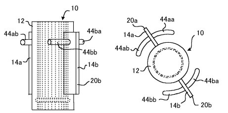
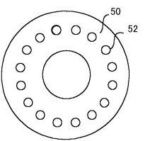
回動ピストン10は、下図に示すようなものです。左の図はそれを側面から見た図であり、中程の図はそれを上面から見た図です。またハウジング16の底壁部50には、それを下から見て下図右に示すように多数の孔52が設けられています。
そして、このハウジング底壁部50を覆うように下図に示すような円板状のノズル板54が回動可能に取り付けられており、その回動加減により孔52の開口度が調節されるようになっています。左の図(A)は全開状態を、右の図(B)は全閉状態を示しています。
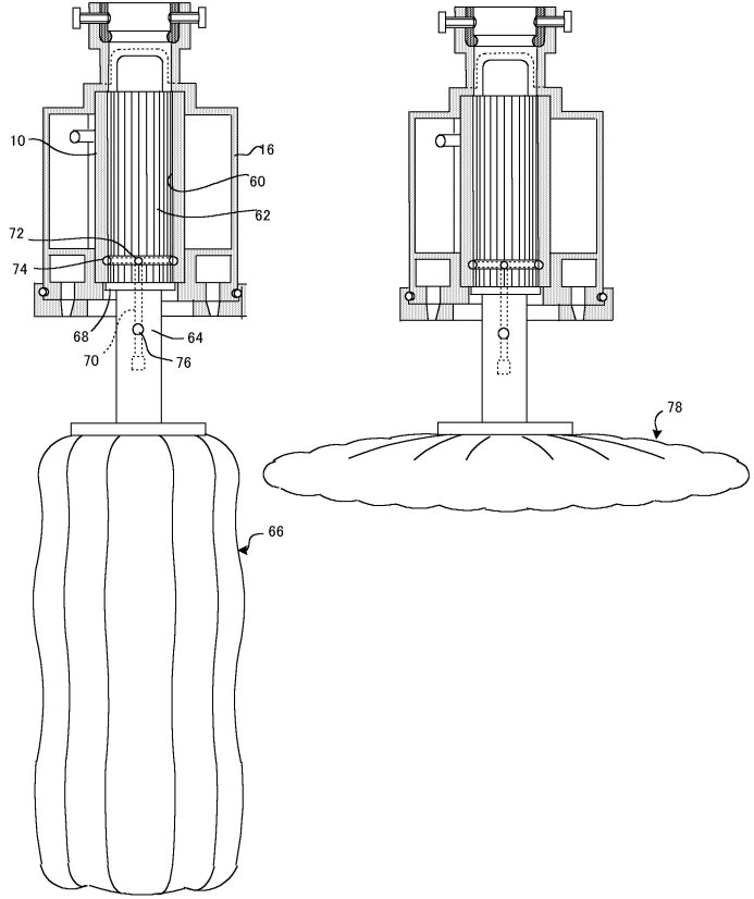
以上のような装置をねじ40にて水道の蛇口に取り付けた上で、単に水を得たいときには、水は回動ピストン10の中心部を貫通する雌型スプライン60内を通って通常の蛇口からの流出と変わりなく流出します。そして、水道蛇口の静水圧エネルギを食器の洗浄に有効に利用したいときには、ブラシ66または78を下図のように、その柄に設けられた雄型スプライン62の部分にて回動ピストン10の雌型スプライン60に差し込むように取り付けます。
回動ピストン10の雌型スプライン60にブラシの雄型スプライン62が差し込まれると、雌型スプライン60の孔が雄型スプライン62により塞がれ、水はハウジング上部の給水ポート28a、28bより環状シリンダ室42a、42b内へ流入し、回動ピストン10を回動させ、排水ポート32a、32bより環状水路46へ流れ、孔56を経てブラシの周りに散水状態に噴出されます。
給水ポート28a、28bより環状シリンダ室42a、42b内への水の送り込みは、給水ポート28a、28b内に設けられた切換弁36a、36bが、回動ピストン10の回動に伴ってその切換弁駆動ピン44aa、44ab、44ba、44bbにより叩かれて切り換わることにより反転します。
即ち、今、回動ピストン10が3段目の図の左図に示す位置にあるときから出発すると、この状態では、切換弁36aは回動ピストンの切換弁駆動ピン44aaによって1段目の図の右図に示す位置に切り換えられ、切換弁36bは回動ピストンの切換弁駆動ピン44bbによって切換弁36aとは反対の位置に切り換えられているので、給水ポート28aからの水は切換弁36aにより3段目の図の左図で見て回動ピストンの板状部14aの右側の空間へ導入され、また給水ポート28bからの水は切換弁36bにより3段目の図の左図で見て回動ピストンの板状部14bの左側の空間へ導入されます。これによって回動ピストンは3段目の左図で見て図示の位置より反時計回りに駆動され、終には3段目の図の右図に示すように回動ピストンの切換弁駆動ピン44baが切換弁36aに突き当り、切換弁36aの傾きを1段目の図の右図に仮想線にて示す位置へ反転させたところで停止します。このとき切換弁36bもまた切換弁駆動ピン44abにより3段目の図の左図の位置より右図の位置へ反転されます。
これより、今度は、給水ポート28aからの水は切換弁36aにより3段目の図の右図で見て回動ピストンの板状部14bの左側の空間へ導入され、また給水ポート28bからの水は切換弁36bにより3段目の図の右図で見て回動ピストンの板状部14aの右側の空間へ導入されます。これによって回動ピストンは3段目の右図で見て時計回りに駆動され、終には3段目の左図に示す位置に来ます。
こうして回動ピストン10は反時計回りと時計回りの半回転を交互に繰り返し、それに伴ってブラシが往復回動され、回動ピストン10を駆動した後の水は、ハウジング底壁部の孔52よりノズル板54にて適当に絞られつつブラシの周りに噴射されます。
【特許請求の範囲】
【請求項1】
円筒部と該円筒部の外面より半径方向に突き出た板状部とを備えた回動ピストンと、
前記回動ピストンを前記円筒部の中心軸線の周りに回動可能に支持する軸受部と、前記回動ピストンが前記軸受部により支持されて前記中心軸線の周りに回動するとき前記回動ピストンの前記板状部の縁を摺接させる環状の内壁面を呈する環状壁部とを備えたハウジングと
を含み、
前記回動ピストンと前記ハウジングとは、前記回動ピストンが前記ハウジングの前記軸受部により前記中心軸線の周りに回動可能に支持されたとき、前記回動ピストンと前記ハウジングの間に環状のシリンダ室を形成し、前記回動ピストンの前記板状部は前記環状のシリンダ室を横切って該環状リンダ室を前記板状部の一方の側にあるシリンダ室空間と前記板状部の他方の側にあるシリンダ室空間とに仕切るようになっており、
前記ハウジングは、更に、水道の蛇口を挿入される孔と該孔に挿入された蛇口より受け入れた水を前記環状シリンダ室へ向けて導く給水ポートとを備えた給水構造部と、前記環状シリンダ室より水を排出する排水ポートを備えた排水構造部と、前記給水ポートより前記環状シリンダ室を経て前記排水ポートに至る水の流路を切り換える切換弁とを有し、前記切換弁は前記給水ポートを前記環状シリンダ室の該切換弁より一方の側に延在する部分に接続し且つ該切換弁より他方の側に延在する部分から遮断すると同時に前記排水ポートを前記環状シリンダ室の該切換弁より前記他方の側に延在する部分に接続し且つ該切換弁より前記一方の側に延在する部分から遮断する第一の切換位置と前記給水ポートを前記環状シリンダ室の該切換弁より前記他方に側に延在する部分に接続し且つ該切換弁より前記一方に側に延在する部分から遮断すると同時に前記排水ポートを前記環状シリンダ室の該切換弁より前記一方の側に延在する部分に接続し且つ該切換弁より前記他方の側に延在する部分から遮断する第二の切換位置との間に切り換えられるようになっており、
前記回動ピストンは、前記板状部が前記環状シリンダ室に沿って一方向へ向かう回動の終端位置に達したとき前記切換弁を前記第一の切換位置へ駆動し、前記板状部が前記環状シリンダ室に沿って他方向へ向かう回動の終端位置に達したとき前記切換弁を前記第二の切換位置へ駆動する切換弁駆動手段を備えており、
前記回動ピストンの前記円筒部にはブラシが一端部にて取り外し可能に挿入されて前記円筒部内の空間を閉塞し且つ前記回動ピストンと共に回動するようになっていることを特徴とする食器洗浄器。
【請求項2】
前記回動ピストンの前記板状部は前記円筒部の中心軸線の周りに等隔置角にて隔置されて複数個設けられており、それに対応して前記給水ポート、前記排水ポート、前記切換弁もそれぞれ同数が等隔置角にて隔置されて設けられていることを特徴とする請求項1に記載の食器洗浄器。
【請求項3】
前記排水構造部は、更に、前記排水ポートに続いて前記環状シリンダ室に沿って環状に広がる環状水路と該環状水路に沿って隔置され該環状水路より水を噴出させる複数の噴水孔を備えていることを特徴とする請求項1または2に記載の食器洗浄器。
【請求項4】
前記ハウジングの前記排水構造部は、更に、前記噴水孔の開口度を全開と全閉の間で調節する噴水孔開口度調節手段を備えていることを特徴とする請求項3に記載の食器洗浄器。
Topへ戻る
高さ変更可能な吊り革
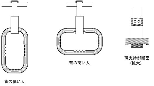
世の中には背の高い人も背の低い人もいます。近年、新しい電車では、出入口部に設けられた吊り革は座席部に設けられた吊り革より幾分高くされているようですが、これは多分、乗り降りに際して人が出入口部を通るとき、吊り革が背の高い人の頭に触れないようにするためであろうと思われます。その理由はともかく、、背の高い人が座席の前に立つこともあれば、背の低い人が出入口部に立つこともあり、或る人には時として吊り革の位置は低過ぎ、また或る人には時として吊り革の位置は高過ぎます。吊り革の高さは、掴まる人の背の高さに応じて、少なくとも高低の2種類に、その場で直ちに且つ容易に変更できるようになっているべきでしょう。
そこで、下図に示すような高さ変更可能な吊り革を提案します。
【特許請求の範囲】
【請求項1】
下端に環状のグリップ支持具を備えた吊り部材と、前記グリップ支持具の環に通された長方形状の環のグリップとを含み、前記グリップの長方形状の環の各辺の中央部の内側には人の手の人差し指、中指、薬指、小指の内側の曲面を連ねた4つの山形に対し補形をなす波形窪みが形成されており、前記グリップ支持具の環の内側のグリップ受面には前記波形窪みに対し補形をなす山形部が形成されており、前記グリップが縦長の姿勢で使用されるか横長の姿勢で使用されるかにより背の低い人または背の高い人に適したグリップ位置を呈するようになっていることを特徴とする吊り革。
Topへ戻る
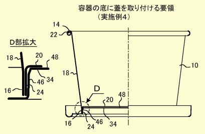
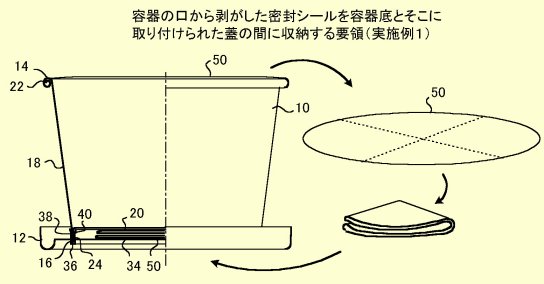
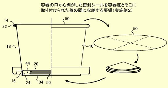
カップの底に蓋を接合できるアイスクリーム容器
アイスクリームを食べるに当たって、カップより取り外された蓋は、無用の邪魔ものとなります。食卓でアイスクリームを食べる場合や、公園のベンチ等であっても、近くにごみ箱があればよいのですが、そうでないとき、蓋は不用意に投棄されたり、アイスクリームを食べ終わったらカップと共にしかるべきところに廃棄するつもりでいても、そのまま置き忘れられて、環境汚染を起こす虞れがあります。また、紙や薄い合成樹脂シートよりなるアイスクリーム容器は、カップの縁に玉縁が形成されたり、周壁の底部が底壁シートの周縁部との接合によって補強されたりしていても、全体としては柔らかくて変形しやすく、掴みにくいものです。特に中身が減ってくるにつれてそれは顕著になります。また、紙や薄い合成樹脂シートよりなるカップは断熱性に乏しいので、指先にて直接つかむと、指先は過冷されて不快であると同時に、カップ内のアイスクリームは指先から伝わる熱により溶かされます。
そこで、アイスクリームを食べるに当ってカップより取り外された蓋の適切なる処分を図ると同時に、この蓋を利用してアイスクリームを食べやすくするアイスクリーム容器を提案します。
【特許請求の範囲】
【請求項1】
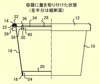
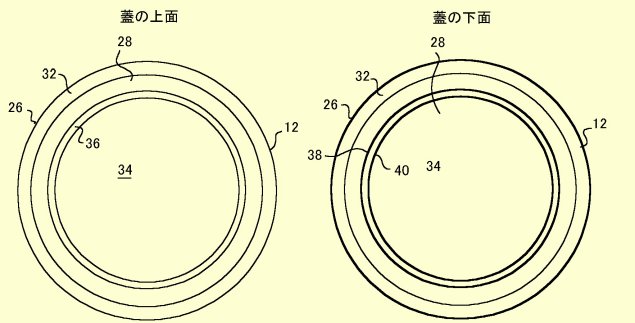
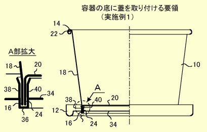
開口を縁取る円形の上縁より円形の下縁へ向けて縮径する逆円錐台状の筒状周壁と前記筒状周壁内の底部に張設された底壁とを有するカップと、前記カップの前記開口を閉じる蓋とを組み合わせたアイスクリーム容器にして、前記蓋の裏側に前記カップの前記周壁の下端部と嵌め合わされて前記カップと前記蓋とを摩擦係合により一体に結合せしめる環状受け面が形成されており、前記底壁は前記筒状周壁の下縁より上縁の側に変位して設けられ、前記蓋の前記環状受け面は前記カップの前記周壁の前記底壁より下方にある部分の外側および内側の両方に接触する2つの環状面であることを特徴とするアイスクリーム容器。
【請求項2】
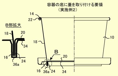
開口を縁取る円形の上縁より円形の下縁へ向けて縮径する逆円錐台状の筒状周壁と前記筒状周壁内の底部に張設された底壁とを有するカップと、前記カップの前記開口を閉じる蓋とを組み合わせたアイスクリーム容器にして、前記蓋の裏側に前記カップの前記周壁の下端部と嵌め合わされて前記カップと前記蓋とを摩擦係合により一体に結合せしめる環状受け面が形成されており、前記蓋の前記環状受け面は前記カップの前記周壁の下端部の外側にのみ接触する1つの環状面であることを特徴とするアイスクリーム容器。
【請求項3】
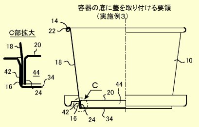
開口を縁取る円形の上縁より円形の下縁へ向けて縮径する逆円錐台状の筒状周壁と前記筒状周壁内の底部に張設された底壁とを有するカップと、前記カップの前記開口を閉じる蓋とを組み合わせたアイスクリーム容器にして、前記蓋の裏側に前記カップの前記周壁の下端部と嵌め合わされて前記カップと前記蓋とを摩擦係合により一体に結合せしめる環状受け面が形成されており、前記底壁は前記筒状周壁の下縁より上縁の側に変位して設けられ、前記蓋の前記環状受け面は前記カップの前記周壁の前記底壁より下方にある部分の内側にのみ接触する1つの環状面であることを特徴とするアイスクリーム容器。
【請求項4】
前記蓋の前記環状受け面より内側に位置する部分は、前記カップの前記周壁の下端部が前記蓋の前記環状受け面と嵌め合わされたとき、前記カップの前記底壁との間に前記カップの開口端を密封するシールの剥がしたものを折り畳んで収納する空間を残すようになっていることを特徴とする請求項1~3のいずれかに記載のアイスクリーム容器。
Topへ戻る
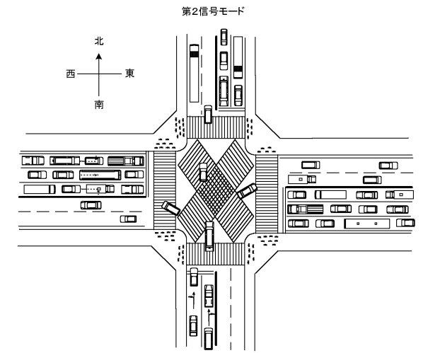
青信号の有効度を100%とする交差点信号機
一般の交差点では、進行方向の信号が青になっても、右折車は対向車がある限り進行できず、また対向車が無く、或いは対向車の合間を縫って対向車線を横切っても、右折後の車線を横切る横断歩道上に歩行者がいれば、右折車はそこで一時待機を余儀なくされ、後続右折車に進路を空けることができないので、後続右折車は対向車の合間を縫って右折進行することができません。また左折に於いても、左折後の車線を横切る横断歩道上に歩行者がいれば、左折車はそこで一時待機を余儀なくされ、後続左折車に進路を空けることができないので、後続左折車は進行することができません。こうして、交差点に於いては、多くの車輌にとって、青信号の期間が無駄に費やされる事態が多発しています。
自車の走行帯域に対する信号が青であるにも拘わらず車輌が進行できないということは、その間、青信号が有効に機能していないということを意味します。これは、交差点に於ける従来の交通整理が、交差点の通行を2つの交差する道路の間で切り換えるという概念に基づいていることに起因しています。
そこで、考えを改め、一つの道路を進行方向が対向する2つの車道と認識し、交差点では互に干渉する4つの車道が交わると考え、青信号は4つの車道の各一つについて順次付与することにすれば、青信号の下に各一つの車道より交差点に進入する車輌は、当該車道に対する信号が青である間、対向車や横断歩道上の歩行者により進行を妨げられることなく確実に交差点を通過できるので、青信号の有効度を100%とすることができます。またこの場合、青信号で交差点に進入した車輌は、直進、左折、右折に関わらず、確実に交差点を通過できるので、4車道の各々への青信号時間の適切な配分は、交差点より上流側における各車道の混み具合の対比に基づいて正確に決定できます。4車道の各々に整列待機した車列の長さは、現在の画像処理技術によれば容易に把握できるので、コンピュータは、知る術もない各車輌の運転者の直進、左折、右折の意志に構うことなく、画像処理手段がもたらす各流入車道の混み具合に応じて、各車道への青信号時間の時々刻々の最適配分を演算すればよいのであり、これによって各交差点、更には市街地全体、の交通整理のコンピュータによる最適制御が可能となる筈です。近時、囲碁や将棋のコンピュータによる対局が種々試みられているようですが、今や多様に変化する状況に対し最適解を求めるコンピュータの能力を市街地全体の交通整理にも生かす時がきていると思います。
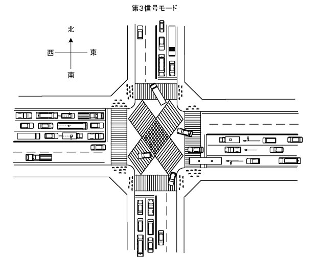
以下にそれを図示します。
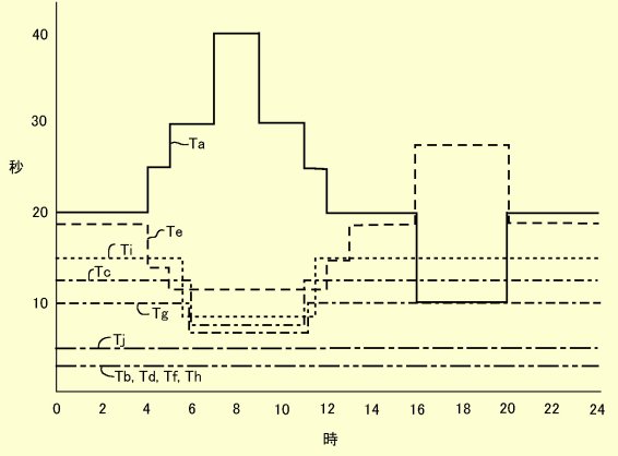
道路は左側通行とし、歩行者横断歩道がないところでは、下記の第1~第4の信号モードを、歩行者横断歩道があるところでは、これに第5の信号モードを加えた第1~第5の信号モードを、それぞれの信号モードの時々刻々変化する必要度の相対比に見合った持ち時間で、順に循環させるものとします。現在の2モード切替では、信号待ちは長くて1分半程であり、この程度の時間が人が信号待ちに苛立たない限界のようです。しかし、車の運転者は、自分の信号が青になれば、その間、確実に交差点を通行でき、しかも直進、左折、右折が自由となれば、1分半よりはもう少し我慢できるのではないでしょうか。また歩行者も、スクランブルで渡れれば、対角方向へも一度の信号で渡れるので、1分半よりはもう少し我慢できるのではないでしょうか。そこで、もし例えばもう後1分、即ち2分半まで我慢してもらえば、1信号モード当たり30秒になります。30秒あれば、かなりの数の車が交差点を通過でき、また歩行者も交差点を安全に渡れます。またこれは2分半を5信号モードに均等に分けた値であり、車線の混み具合に差があれば、混んでいる車線は空いている車線より時間を分けてもらうことができ、また空いていて30秒も要しない車線があれば、次の信号モードへの切換を早めてモード循環の速度を上げることもできます。


第1~第5信号モードは以下のようなタイムスケジュールで切り替えられます。
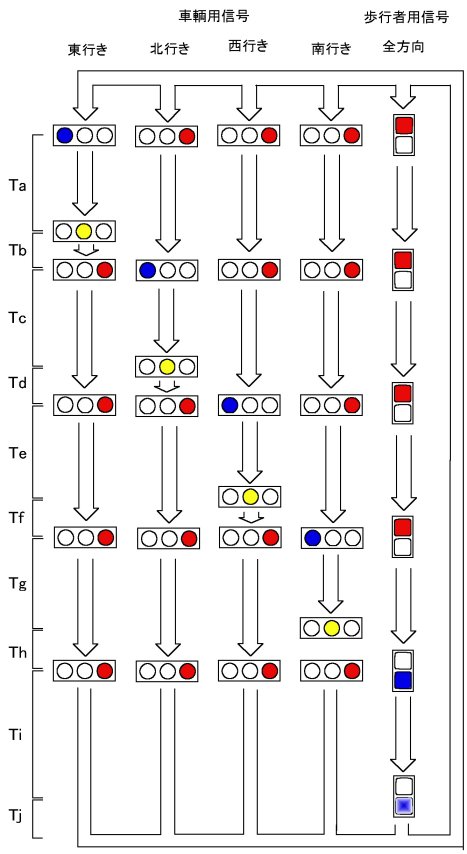
上記の第1~4信号モードがこの順に循環されれば、一つの信号モードにて交差点を最後に走行する車輌は、他のいかなる信号モード循環順序におけるよりも、次の信号モードの青信号で交差点を通過し始める車輌からより大きく隔たることができます。
タイムスケジュールの一例は以下のようなものです。
既存の信号機のハードウェアはそのまま使えます。
また多発している右折車と対向直進車の衝突事故はなくなります。
【特許請求の範囲】
【請求項1】
各々が互に対向する車輌走行帯域を有する第一および第二の道路が交わる交差点の信号機にして、前記第一および第二の道路は左側通行道路であるとして、
前記第一の道路の一方の車輌走行帯域に対する信号灯を青とし、その他の車輌走行帯域の全てに対する信号灯を赤とし且つ歩行者の一切の交差点通過を禁止する第一の信号モードと、
前記第一の道路の他方の車輌走行帯域に対する信号灯を青とし、その他の車輌走行帯域の全てに対する信号灯を赤とし且つ歩行者の一切の交差点通過を禁止する第二の信号モードと、
前記第二の道路の一方の車輌走行帯域に対する信号灯を青とし、その他の車輌走行帯域の全てに対する信号灯を赤とし且つ歩行者の一切の交差点通過を禁止する第三の信号モードと、
前記第二の道路の他方の車輌走行帯域に対する信号灯を青とし、その他の車輌走行帯域の全てに対する信号灯を赤とし且つ歩行者の一切の交差点通過を禁止する第四の信号モードと
を、交差点を上から見て、信号灯を青とする車輌走行帯域が反時計回り方向に進行するよう切り換えられるように、循環させることを特徴とする信号機。
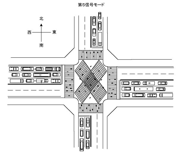
【請求項2】
循環させる信号モードに第五の信号モードを追加して含み、前記第五の信号モードに於いては前記車輌走行帯域の全てに対する信号灯を赤とし、歩行者に交差点の自由な通過を許可することを特徴とする請求項1に記載の信号機。
【請求項3】
1週間内の曜日および1日の内の時間帯の少なくとも一方に応じて循環させる前記信号モードの各一つの実行時間が個別に設定されることを特徴とする請求項1または2に記載の信号機。
Topへ戻る
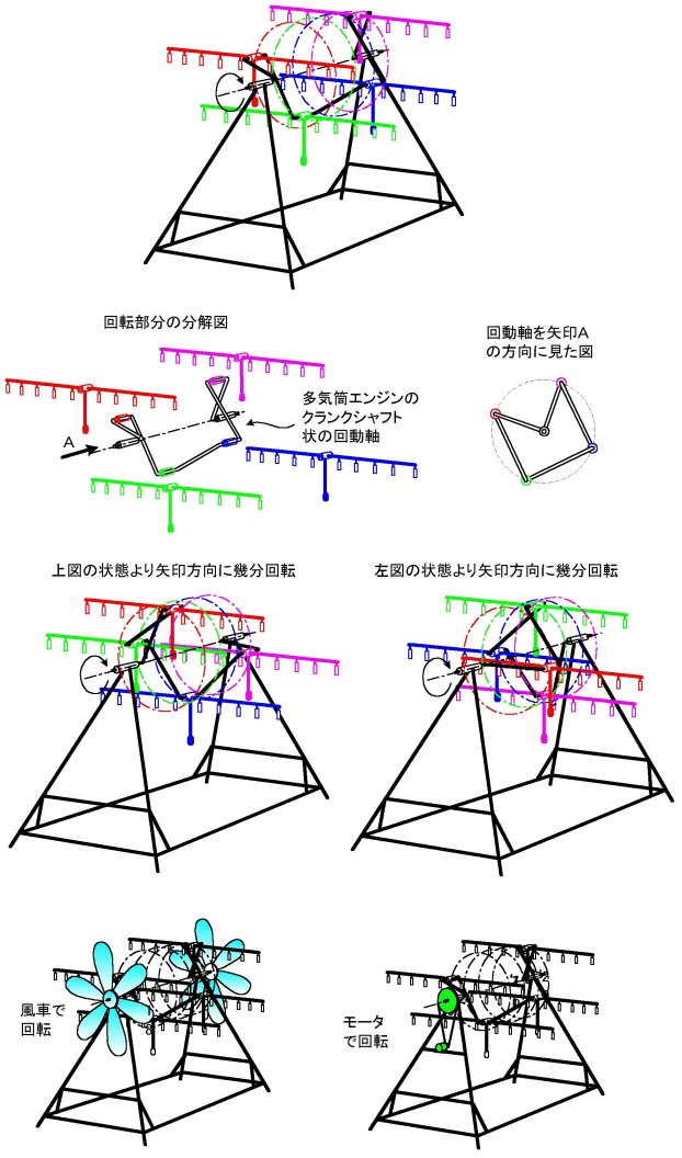
回転式物干し装置
マンションのベランダや室内等の比較的狭いスペースでも沢山の洗濯物を短時間で乾かすことができる回転式物干し装置を提案します。
特徴は、複数本の竿がそれぞれ垂直の平面に沿って相互に変位しつつ回転することであり、狭いスペース内に高密度で洗濯物を干しても、各洗濯物の周りの空気を逐次更新し、洗濯物からの水蒸気の発散を速めることです。
【特許請求の範囲】
【請求項1】
支持枠体と、一つの主回動軸線に沿って互いに同心に整合し且つ該主回動軸線に沿って互いに隔置された状態に前記支持枠体により支持された第一および第二の主軸受と、前記第一の主軸受により第一の端部を回動可能に支持されまた前記第二の主軸受により第二の端部を回動可能に支持されて前記第一と第二の主軸受の間にて前記主回動軸線の周りに回動する回動枠体とを有し、
前記回動枠体は、前記第一の端部より前記第二の端部へ向けて前記主回動軸線に沿う方向に順に配列され且つ前記主回動軸線に対し直角の方向に隔置された複数の副軸受と、前記複数の副軸受のうちの互に隣接する副軸受の内側部材どうしを連結する中間連結部材と、前記複数の副軸受のうちの前記第一の端部に隣接する副軸受の内側部材と前記第一の端部とを連結する第一の端部連結部材と、前記複数の副軸受のうちの前記第二の端部に隣接する副軸受の内側部材と前記第二の端部とを連結する第二の端部連結部材と、前記複数の副軸受の各々の外側部材により支持されて前記主回動軸線に対し直角の方向に延在する干し物懸架用竿部材とを含んでおり、前記干し物懸架用竿部材には前記副軸受により支持されている位置から下向きに延在して該干し物懸架用竿部材を水平姿勢に付勢する重錘棒部材が取り付けられていることを特徴とする回転式物干し装置。
【請求項2】
前記複数の副軸受は前記主回動軸線に沿う方向に見て該主回動軸線の周りに均等に角隔置されていることを特徴とする請求項1に記載の回転式物干し装置。
【請求項3】
前記干し物懸架用竿部材には干し物を挟んで懸架する干し物挟みが取り付けられていることを特徴とする請求項1または2に記載の回転式物干し装置。
【請求項4】
前記回動枠体には風を受けて該回動枠体を前記主回動軸線の周りに回動させるモーメントを生じる風車が取り付けられていることを特徴とする請求項1~3のいずれかに記載の回転式物干し装置。
【請求項5】
前記回動枠体を前記主回動軸線の周りに回動させる電動駆動手段を有することを特徴とする請求項1~4のいずれかに記載の回転式物干し装置。
Topへ戻る
高層建物用避難梯子
高層建物には火災発生等の非常事態に備えた非常用階段が備えられており、また高層マンション等ベランダのあるところでは、更にベランダの一隅に非常用ハッチが設けられています。しかし、そのように非常用階段や非常用ハッチが設けられていても、火災発生の位置や風向きによる火周りの具合によっては、非常用階段や非常用ハッチへ近付けない場面に遭遇しないとも限りません。そのようなときにも、最後まで確実に残される逃げ場所は、ベランダのように解放された場所の火や煙より最も離れた個所です。そして、そのとき、もし手元に避難梯子があれば、下の階へ脱出できます。ただ、手に持ってベランダを走れるような手軽な避難梯子で降りられるのは、1階分か高々2階分でしょう。しかも、高層建物では、1階分か2階分下の階に降りても、その階の窓は全部施錠されていたり、また1階分か2階分下の階が上の階より安全であるとの保証はなく、それより更に下の階へ引き続いて降りられないのでは、殆ど意味がありません。
そこで、手に持ってベランダを走れるような手軽なものであって、何階分でも降りられる避難梯子を提案します。ただ、ここに提案する避難梯子は、何階分でも降りられるものとはいえ、手軽な構造であるだけに、それを伝って高層のベランダ間を降りるには、相当の勇気を必要とするものです。しかし、溺れる者は藁をも掴むといいます。生きるか死ぬかの瀬戸際であれば、手軽な構造の避難梯子でも、必死になれば、それなりに役立つものですし、また必死で降りるうちに徐々に慣れてくることが期待されます。そもそも、各人についてみれば、そのような場面に遭遇する確率は極めて低いものです。それでも、高層マンション等に住む限り、絶対にないとはいえません。いざという時のために最後の命綱の備えがあれば安心です。
以上の趣旨から、ここに提案する高層用避難梯子は、あくまで、それが実際に使用される確率とそれに備える費用との間のバランスを図ったものです。この備えが無駄に終われば、それはそれで幸運なことです。そのとき無駄に失われる費用はごく僅かです。
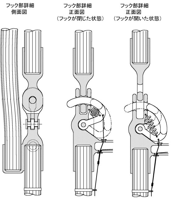
ポイントは、1階分程度の縄梯子の両端部に、フックの開閉によりベランダの手摺等に掛け止めできる取り付け装置を設けておき、フックは直に開閉できるだけでなく、他端部からもひもを引っ張ることにより遠隔操作で開けるようにしておくことです。使用に当たっては、先ず、今自分がいる階のベランダの手摺等に縄梯子の一端を取り付け、縄梯子を下の階まで垂らします。そして、縄梯子を伝って下の階に降ります。次いで、先ず上から垂れている縄梯子の下端部を今降りてきた下の階のベランダの手摺等に取り付けます。その後、ひもを引っ張って上の階に取り付いている縄梯子の上端部にあるフックを開き、縄梯子の上の階への取り付けを解除します。これより縄梯子は上から落ちて来て、今いる階より更に下の階へ向けて垂らされた状態となります。以上の繰り返しにより、何階でも降りることができます。

【特許請求の範囲】
【請求項1】
高層建物の1階差ないし数階差の高さに相当する長さの梯子部と、前記梯子部の両端に設けられた高層建物の欄干等への解除可能な取付け手段とを有し、該取付け手段は前記梯子部の両端のいずれの部位に於いても前記欄干等への取付けを解除できるようになっており、前記梯子部の一端をそこに設けられている前記解除可能な取付け手段によりその階の欄干等に取り付け、これより前記梯子部を他端まで下方へ垂らし、前記梯子部を伝って下の階に移り、前記一端の解除可能な取付け手段を下の階から遠隔操作により解除できるようになっていることを特徴とする避難梯子。
【請求項2】
前記梯子部は、一対のロープとその間に橋渡しされた複数の横木とからなることを特徴とする請求項1に記載の避難梯子。
【請求項3】
前記取付け手段は、一端にて前記梯子部の一端に固定されて欄干等の一部に巻き掛けられるロープ片と、該ロープ片の他端を前記梯子部の前記一端に取外し可能に係止する係止装置を含んでいることを特徴とする請求項1または2に記載の避難梯子。
【請求項4】
前記係止装置は、前記梯子部の前記一端の側に設けられたフック孔と前記ロープ片の前記他端の側に設けられたフック孔と、前記梯子部の前記一端側のフック孔と前記ロープ片の前記他端側のフック孔とを重ね合わせた重合孔に選択的に通されるフックと、該フックを前記重合孔に通された位置へ付勢するばねと、前記ばねの弾力に抗して前記フックを前記重合孔より引き抜く引張り紐とを含んでいることを特徴とする請求項3に記載の避難梯子。
【請求項5】
前記フックは前記重合孔に通された位置と前記重合孔より引き抜かれた位置との間に回動する回動フックであることを特徴とする請求項4に記載の避難梯子。
【請求項6】
前記取付け手段は、前記梯子部の両端の各々に一対として設けられていることを特徴とする請求項1~5のいずれかに記載の避難梯子。
Topへ戻る
タブレット用着脱式カメラ
昨今インターネットを通してタブレット対話をすることが盛んになってきていますが、対話者の顔を写すカメラの眼孔はタブレットの縁枠に開口しているので、タブレットの画面に映る相手の目は相手のタブレットの姿勢に応じて伏目だったり、上目だったり、横眼だったりで、こちらを向いてはくれず、お互い相手と目が合わない対話を強いられています。そこで、タブレット対話をするときだけ、タブレットに装着されることによりカメラの眼孔をタブレットの画面の中央に位置させ、お互いに目を合わせて対話ができるようにするタブレット用着脱式の外付けカメラを提案します。
Topへ戻る
恐竜の脚は細過ぎる
(弁理士会会誌「パテント」1991年4月号に掲載)
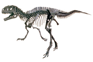
過日、幕張メッセにて開催されていた学研、TBS主催の大恐竜博を見に行き、ティラノサウルスを始め数頭の大恐竜の全身骨格を見て、その脚がいかにも細く、虚弱であることに驚かされた。
地上最強の肉食恐竜として良く知られているティラノサウルスの全身骨格は、会場に於ける注目の出し物であった。その主骨格は、長径1メートルを優に越えると思われる巨大な卵形の頭骨から、大抱えの肋骨を経て、倒木のような尾骨に至るまで、全長14,
5メートルにも及んでいる。ところが、その壮大な主骨格の中央部を支える2本の脚の骨は、甚しく細く、しかもそれらは、常時いわゆる中腰の姿勢に、膝関節を大きく曲げた構造のものである。この恐竜の体重は、推定約6トンとのことであった。
現在陸上で最大の重量を有する動物であるアフリカ象は、4脚で立っており、これら4脚は、いずれも丸太を縦にした様にほぼ垂直に延び、足先は丸太の直角端面をそのまま地面に押し当てたような形になり、脚に曲げ荷重をかけることなく、大きな体重を支え易いようになっている。しかるに、ティラノサウルスは、2脚で歩行し、しかもその脚は、上記の通り膝関節を大きく曲げた中腰姿勢にある。しかも主骨格と脚の接合部には、大した骨盤らしきものも見当たらない。更に足の先は3本に分岐した爪となっており、これらの爪は、何れも先端へ向けて、地面に対し
30o 程度下向きに傾斜して延び、その先端のほんの僅かな部分にてのみ地面に接するようになっている。これらのことから察するに、かのティラノサウルスは、6トンの体重を2本の脚で支え、爪先立った中腰姿勢で地上を闊歩していたことになる。
ティラノサウルスと比較しては甚だ失礼だが、2本の脚で巨大な体を支える例として、あの小錦関の勇姿が想い浮かぶ。小錦関は、力士という職業柄、脚腰を特別に鍛えており、240kg
の巨体にも拘らず、いざというときの体の動きは、常人のそれより遥かに敏捷である。しかし、一息入れた後の様子には、随所に、体重ももうこれが限界であるという雰囲気が漂っている。しかし、ティラノサウルスの体重は、小錦関のそれの25倍だったのである。そして、ティラノサウルスもまた、逃げる獲物を追いかけるため、相当敏捷に体を動かしていた筈である。
大恐竜博には、4脚にて立つ巨大な恐竜の全身骨格も同時に展示されていた。それらの4脚もまた、何れも膝部にて大きく折れ曲がり、足先は爪に分かれて爪先立っており、正に跳躍に適した構造に見受けられた。
材料力学に於ける初歩的事項であるが、材料の機械的強度の基本である引張り強さ或いは圧縮強さは、材料の断面積に比例し、従ってそれは、所謂大きさ、即ち一次元寸法、の2乗に比例する。これに対し、材料の重さは、一次元寸法の3乗に比例する。従って、動物や生きた植物の如く、自分の力で自重を支えなければならないものにとっては、その大きさが大きくなればなるほど、体の各局部に作用する荷重のきつさは、加速度的に増大する。即ち、同じ体形ならば、身長が2倍になれば、体の各局部に於ける応力は2倍になり、身長が3倍になれば、応力は3倍になる。従って、身長20メートルのキングコングは、身長2メートルのゴリラに比して、その骨や筋肉が10倍も良質にできていなければならない。ここに、生物の体格的発達に関して、自ずと限界があると思われる。
大恐竜博には、その骨格から推測して作られたティラノサウルスの模型や、その徘徊中の想像図も展示されており、その脚は確かに太く、筋肉の塊りのようであった。しかし、筋肉は専ら引張り力を生ずる手段であり、脚にかかる上体の重量は、究極的にはその骨によって支持されざるをえない。
現在の地球表面上での 9.80 m/sec2なる重力加速度の下では、2本の脚で立つ動物が体格的に発達し得る限界は、その体重が小錦関のそれの 240kg に達する程度迄であり、それ以上に体重が増しては体の動きが損なわれ、ましてそれが野生の肉食動物であって、逃げる餌を捕食しなければならない場合には、それ以上の体重への進化による発達は無理ではなかろうか。
では、何故、ティラノサウルスは、2本の脚で立ちながら、6トンの体重まで進化し得たのであろうか。それは、6500万年前まで、地球表面に於ける重力加速度は、現在の値よりも遥かに小さかったからである、と私は考える。そして、6500万年前の或る時、地球表面上の重力加速度は、一挙に現在の値に増大し、ティラノサウルスの如き巨大な恐竜だけでなく、それより小さい中型或いは小型の爬虫類やその他の動物であっても、小さな重力加速度の下でその時までに爪先立つような軽快な姿態に発達していたものは、忽ちその自重に耐えられなくなって死滅し、またそれまで地上に繁茂していた古代しだの如き巨大植物も、次第に滅びていったものと推測される。
この地球表面上に於ける重力加速度の突然の増大は、地球の自転速度の突然の低下による。但し、これは、全て仮説である。
現在、地球は24時間で1回転している。地球の半径は、赤道上で6380kmであり、半径 r、角速度ωによる回転によって生ずる遠心加速度は、 rω2 であるから、現在赤道上にある物体に作用している遠心加速度は、0.0337 m/sec2 である。現在、地球の表面上における重力加速度は、緯度によって多少異なるものの、約 9.807 m/sec2 であるとされているので、約 9.841 m/sec2 の重力加速度が、地球を構成する物質による万有引力として作用している。
そこで、6500万年前まで、地球が2時間で1回転していたとし、地球の内部のマグマは、ガスを含んでいて幾分圧縮性であり且軟かいので、地球の自転速度がより大きければ、地球の体積は今より幾分大きく、またそれはかなり扁平化し、赤道上での直径は、今より大きくなろうが、今簡単のため、この変形を無視して考えても、地球表面の赤道上に於ける遠心加速度は、4.860
m/sec2 となり、従って、ここでの見掛けの重力加速度は、4.981 m/sec2 となる。これは、物の重さが今の 50.1% になることを意味する。逆に、当時のティラノサウルスが、現在なら6トンに達する体重を、その 1/4
の 1.5 トンに感じていたとすると、その時地球は、1時間37分18秒程度で1回転していたことになる。
この巨大な地球がたったの1時間半程で1回転することがあり得るか、と思われる方があるかもしれないが、地球は、僅か365日の間にその直径の73800倍もの距離、即ち1日にその直径の202倍もの距離、をすっとんで走っている高速運動体である。1時間半程かけて1回転するくらいは、お茶の子さいさいではないか。尚、回転数がこの程度まで速くなってくると、1回転当たり1分間の速度の違いによっても、地上での見掛けの重力加速度は大きく異なり、即ち、1回転の時間が1時間34分14秒になると、見掛けの重さは
1/5 となり、更にその時間が1時間32分20秒になると、見掛けの重さは 1/6 となり、その時間が1時間23分19秒になると、遂に重さは零になってしまう。
では、何故、6500万年前の或る時、突然に地球の自転速度が、10分の1以下にも落ちたのか。ここで、高橋実氏の仮説による水惑星(高橋実著「灼熱の氷惑星」1975年原書房)の存在が、一層現実味を帯びてくる。
高橋氏の仮説は、我々の太陽系には、地球軌道に交差する著しい長楕円の軌道に沿って、外径はほぼ地球のそれに等しく、直径の半分を占める中心核と、その周りを覆う厚い水層とを有する惑星が、約
3000 年の周期にて周回しているというものであり、この水惑星は、過去に地球に衝突しており、また地球への過去に於ける最後の接近の際に、地球へ大量の水を浴びせており、それが人類の記憶に残るノアの洪水として伝えられているというものである。尚、上記長楕円の長径は約
300億kmであり、従ってこの惑星は、それが遠日点近くにいるときには、冥王星の軌道半径約 60億kmの約10倍も我々より離れるので、パロマ山の200インチ反射望遠鏡でも見えないそうである。
高橋氏は、現在の太陽系の成因から説き起こし、多数の客観的事象を検証しつつ、上記惑星の存在を極めて理論的に推定しておられる。この惑星は、上記の通り地球と同大で、その表面から半径の半分に至る深さまで水よりなるものであり、地球に接近するときの地球に対する相対速度は、秒速30kmであり、地球の赤道面にほぼ沿う方向に進行し、地球との出会いの際の僅かな時間差により、地球の自転を加速する方向にも、減速する方向にも、地球に接触し得るものである。従って、この水惑星が、その分厚い水層にて地球の片側に、その自転を減速する方向に深く接触すれば、それまで1時間少々にて1回転していた地球は、簡単にその自転速度を現在の速度まで減じるであろう。
地球が1時間半で1回転するときの赤道上での周速は、7.423 km/sec であるから、相対速度 30km/sec の水惑星によって減速されるには、丁度適している。地球が上記水惑星の水深一杯まで深く接触したとすると、接触が始まってから終わるまでの時間は、280 秒程である。この間に、地球の自転速度が1回転/1.5時間より1回転/24時間まで一様に減速されたとすると、その減速の加速度は、24.6 m/sec2、即ち現在の地表の重力加速度(G)の2.5倍である。恐竜達は、或る時突然 2.5G の力で5分間近くも地面に沿って闇雲に引摺られ、それがやっと終わったときには、哀れ彼等は自分自身の重さのために立ち上がることができなくなっていた。但し、この光景は、恐竜の全身化石が豊富に出土する北アメリカでのものである。その時、地球の反対側にあって、水惑星の水層深く突入した、現在の中東地域にあたるところでは、最早生物の痕跡は無く、そこにはただ油混りの砂丘が漠々として広がっていた......但し、このことは、もう既に高橋氏が教示されていることである。
またそれまでの1時間少々にて1回転する自転速度も、もしかすると、それ以前の同惑星との接触による加速によって得られていたのかもしれない。我々の太陽系では、水星、金星の自転速度はそれぞれ 59日、245日であり、火星のそれは 1.03日、木星、土星、天王星のそれはそれぞれ 0.41日、0.43日、0,45日であり、海王星のそれが 0.58日、冥王星のそれが 6.39日である。これら兄弟星の自転速度から見て、もともと1時間少々にて1回転では、速過ぎるかも知れない。
しかし、高橋氏による現在の太陽系の形成過程の説明と物理学的推論によれば、水素と酸素が地球上で出会って水を形成することは殆どあり得ず、地球の水は、ムカシ太陽の超新星爆発後の今日に至る冷却過程に於いて、上記の長楕円軌道を周回する惑星が、酸素および水素が他の元素と化合してしまう前に、太陽に近い位置にて酸素を集め、また太陽より遥かに隔たる位置にて水素を集めることによって作った水を、この惑星より与えられたものである。これは、同じようにして生まれた他の兄弟星が殆ど水を有しないことを考えれば、大いに頷けることであり、地球は、まず上記水惑星との衝突により水を与えられ、その時またはその後の衝突により、その自転速度を加速され、水の存在により生まれた生物が大恐竜に至るまで発達したところで、再度上記水惑星により自転速度を減速されて、今日に至っているのではなかろうか。そして、兄弟星の中では地球のみに特有のようにみえるあの高い山や深い海は、地球の自転速度が減速され、遠心加速度の減少によって地表層に大きな収縮が生じたときに作られたものではなかろうか。現在の太陽系の年齢は、150億年であるとされている。従って、周期
3000年の上記水惑星は、これまでに地球の軌道を 500万回近くも横切っているのである。
最後に、今一度、重力加速度の大きさの意義を考えたい。我々は今、9.80 m/sec2 の重力加速度の場に生活しており、かかる重力加速度の下で質量に作用する重力と慣性力とに基く物体の運動に慣れている。だから、人類が月面に到着し、宇宙飛行士が膝を大きく曲げ、月面をぴょんぴょんと飛び跳ねるようにして歩く様を見て、奇異に感じた。しかし、質量に作用する慣性力に対する重力の割合が小さくなったとき歩行体に生ずる運動は、あのように膝を大きく曲げ、爪先立ってぴょんぴょんと飛び跳ねるようにして歩く運動である。ティラノサウルス他の恐竜の骨格は、まさしくそのような軽快な飛び跳ね歩行に適したものである、と見受けられた。(以上、弁理士会会誌「パテント」1991年4月号掲載による)
検証1:恐竜の絶滅は、隕石の落下により発生した塵により大気が曇り、寒冷の気候が続いたためとの説があるが、これでは同じ冷血の爬虫類でありながら地を這う形態のワニ、トカゲ、ヘビ、カメ等が生き延びたことが説明できない。
検証2:動物は重力より解放されると巨大化し得ることは、鯨が示している。
検証3:地球の表面部は太平洋プレート、北米プレート、フィリピン海プレート、ユーラシアプレート、アフリカプレート等々の集まりよりなっており、これらのプレートは互いに隣接する領域にて互いに他との重なり合いを深める動きをし、地震源や津波源となっている。これは、地球の自転速度が大きい時代に地表部の冷却固化により生成された球殻状の固化層が、地球自転速度の低下に伴う遠心力の消失により収縮して多数のプレートに割れ、今なお全体として収縮しているためであると推測される。もし地球自転速度の低下に伴う遠心力の消失による収縮力が作用しなければ、球殻状の固化層はそのままでいられ、またたとえひび割れてプレートの集まりとなっても、プレートの隣接する領域にて互いに他との重なり合いを深める動きは生じない筈である。
検証4:表面部は冷却固化して球殻となり、その内部はマグマの状態にて1時間半程で1回転していた地球が、球殻部にて回転を制動されて現在の自転状態になったとすれば、その時、球殻内の流動性マグマはその慣性により制動に対する反動として球殻に対し南極側から北極側を見て時計回り方向に回転した筈である。かかるマグマの球殻に対する相対的回転により、球殻とマグマの間には地球の自転軸線を中心とする摩擦摺動が生じ、球殻は摩擦起電力により自転軸線の周りに対称な磁化作用を受け、南極をN極とし北極をS極とする磁石に磁化されたと思われる。
検証5:大恐竜の時代には地表の重力加速度が恐竜の巨大化を許すほど小さかったとすれば、大気もそれ相応に現在のそれより薄かったはずである。ティラノサウルス他の恐竜の肋骨が示す肺の体積は、体の大きさに対比して現在の動物のそれよりかなり大き い。
topへ戻る
Vehicle drive control device in congestion
Since the inter-vehicles distance for
the safe driving is to be taken larger as the vehicle speed increases,
when the vehicles are driven in a longitudinally close proximity as in
a congestion by ensuring the safety while leaving the inter-vehicles distance
as small as possibe to suppress the elongation of the vehicle train, it
is necessary that the inter-vehicles distance at each moment is increased
or decreased to a necessary minimum optimum value in accordance with increase
or decrease of the vehicle speed at the moment.
Further, when it is considered that the
kinetic energy of the vehicle body increases in proportion to the square
of vehicle speed so that the kinetic energy of the vehicle body decreases
acceleratingly as the vehicle speed approaches to zero and thereby the
action and the precision of the inter-vehicles distance control of the
brake system improves so acceleratingly as to allow an acceleratingly contracting
inter-vehicles distance, while in the vehicle speed region above the slow
speed driving the kinetic energy of the vehicle body which increases in
proportion to the square of vehicle speed lowers the action and the precision
of the inter-vehicles distance control of the brake system so acceleratingly
as to necessitate an acceleratingly increasing estimation of the safe inter-vehicles
distance, the inter-vehicles distance to meet with the vehicle speed should
desirably follow an inclination curve which is upwardly convex in the vicinity
of zero vehicle speed and downwardly convex in the vehicle speed region
above the slow speed driving, as exemplarily shown in the following figure.
However, since the inter-vehicles
distance is not dependent only upon the own vehicle speed but changes in
accordance with the relative relation between the vehicle speeds of the
preceding vehicle and the own vehicle, the control of the inter-vehicles
distance needs to pay an attention to the vehicle speed of the preceding
vehicle, and compels very troublesome and tiring operations of the accelerator
pedal and the brake pedal if the inter-vehicles distance is to be controlled
to such optimum values as exemplarly shown in the above in accordance with
changes of the own vehicle speed when the preceding vehicle repeats the
start, acceleration, deceleration and stop as in the congestion. And
yet, if the inter-vehicles distance is left too much for a thoughtless
safety, the line of vehicles becomes long to aggravate the congestion,
while if the inter-vehicles distance is too shortened, there creeps in
a danger of rear-end collision.
Thus, herein is proposed a vehicle
drive control which leaves the operations of the accelerator pedal and
the brake pedal to a computer control in a congestion so as to start, accelerate,
decelerate and stop the own vehicle as following to the start, acceleration,
deceleration and stop of a preceding vehicle while always leaving a proper
inter-vehicles distance which increases or decreases in accordance with
increase or decrease of the vehicle speed as exemplarly shown in the above
figure. By the provision of such a vehicle drive control the driving action in congestion becomes only to finely adjust the steering and it is expected that the fatigue of driving in congestion is much lessened, with the congestion
itself being also lessened by obviating the delay of the succeeding vehicle
in starting and following the preceding vehicle.
The point of the control is to prepare such
a map of "Inter-vehicles distance vs. Target vehicle speed" as
shown hereinunder to correspond to a desirable "vehicle speed vs.
inter-vehicles distance" such as shown above in the electronic computer
of the own vehicle, and, by measuring the distance between the own vehicle
and the preceding vehicle by the radar or the like, the vehicle speed of
the own vehicle is simply controlled at each moment to accord with each
momentary target vehicle speed corresponding to each momentary distance
between the own vehicle and the preceding vehicle. Thus, the control
is to control only one control parameter , "the own vehicle speed", in accordance with changes of only one measuring parameter, "the inter-vehicles distance". When the own vehicle
speed at each moment is controlled to accord with each momentary target
vehicle speed corresponding to the inter-vehicles distance at each moment,
the vehicle speed of the preceding vehicle need not be surmised or measured even in a control for controlling the inter-vehicles distance, so that the Cooperatively Adaptive Cruise Control (CACC) to cope with changes of the vehicle speed of the preceding vehicle is available with no need of the inter-vehicles communication, since the changes of the vehicle speed of the preceding vehicle are grasped
as changes of the relative vehicle speed of the preceding vehicle against
the own vehicle through the changes of the inter-vehicles distance generated
in the interval between each two adjacent moments.
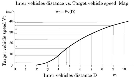
It is now assumed for the simplicity that
the vehicle preceding the own vehicle is running at a constant speed such
as e.g. 15 km/h. If under such a situation the distance between the
own vehicle and the preceding vehicle is larger than a distance such as
4.76 m which corresponds to 15 km/h as viewed in the above map, the own
vehicle is driven to be faster than 15 km/h since the target vehicle speed
to correspond to such an inter-vehicles distance is higher than 15 km/h,
so that the own vehicle runs faster than the preceding vehicle, and therefore,
the distance between the two vehicles will shorten until it reaches 4.76
m. On the other hand, if the inter-vehicles distance is smaller than
4.76 m, the own vehicle is driven to be slower than 15 km/h since the target
vehicle speed to correspond to such an inter-vehicles distance is lower
than 15 km/h, so that the own vehicle runs slower than the preceding vehicle,
and therefore, the distance between the two vehicles will expand until
it reaches 4.76 m. Thus, in any event, the own vehicle will start to follow
the preceding vehicle at a constant vehicle speed of 15 km/h. The
same thing occurs when the preceding vehicle is running at any other constant
speed. Therefore, when it is so adapted that the vehicle speed of
the own vehicle is controlled to a target vehicle speed based upon the
distance from the preceding vehicle according to a map such as examplarily
shown in the above, the own vehicle will follow the preceding vehicle running
at any optional constant speed at the same corresponding constant speed
while keeping an inter-vehicles distance optimally corresponding to the
constant vehicle speed.
Further, when the preceding vehicle starts
to accelerate from a state that the own vehicle is following the preceding
vehicle running at a constant vehicle speed such as e.g. 15 km/h while
keeping the inter-vehicles distance of 4.76 m, the inter-vehicles distance
expands beyond 4.76 m, so that the own vehicle is also accelerated, and
when the acceleration of the preceding vehicle settles at 20 km/h, the
acceleration of the own vehicle also settles at 20 km/h, and thereafter
the own vehicle follows the preceding vehicle while keeping an inter-vehicles
distance expanded over 4.76 m to correspond to 20 km/h (5.44 m in the above
map). Similarly, when the preceding vehicle starts to decelerate
from a state that the own vehicle is following the preceding vehicle running
at a constant vehicle speed such as 15 km/h while keeping the inter-vehicles
distance of 4.76 m, the inter-vehicles distance contracts below 4.76 m,
so that the own vehicle is also decelerated, and when the deceleration
of the preceding vehicle settles at 10 km/h, the deceleration of the own
vehicle also settles at 10 km/h, and thereafter the own vehicle follows
the preceding vehicle while keeping an inter-vehicles distance contracted
below 4.76 m to correspond to 10 km/h (4.14 m in the above map).
When the preceding vehicle stops, the own
vehicle also stops, leaving a distance of 2 m as viewed in the above map
from the preceding vehicle. Thereafter, when the preceding vehicle
starts to proceed, the own vehicle also starts to proceed as the inter-vehicles
distance increases, and when the preceding vehicle increases its speed,
the own vehicle also increases its speed while keeping the inter-vehicles
distance optimally corresponding to its speed.
The digital calculation control by the electronic
computer can be executed cyclically by a minute cycle time such as several
tens of milliseconds. Therefore, when it is so adapted that a follow
control such as mentioned above is executed repeatedly by such a minute
cycle time, the own vehicle will start, accelerate, decelerate and stop
according to the preceding vehicle starting, accelerating, decelerating
and stopping without delay while continually keeping a proper inter-vehicles
distance corresponding to each momentary vehicle speed as controlled by
the follow control executed cyclically by the minute cycle time of several
tens of milliseconds, so that the own vehicle can follow repetitions of
start, acceleration, deceleration and stop of the preceding vehicle as
met in the congestion without delay while continually keeping a proper
inter-vehicles distance which increases or decreases corresponding to increase
or decrease of each momentary vehicle speed.
As a result of such a control, the own vehicle
will start, accelerate, decelerate and stop following to the start, acceleration,
deceleration and stop of the preceding vehicle as shown hereinunder. When
the preceding vehicle starts, accelerates, decelerates and stops slowly,
the own vehicle will start, accelerate, decelerate and stop also slowly
so as to be apart from the preceding vehicle up to a relatively small distance
at the most as shown in the below left figure. When the preceding vehicle
starts, accelerates, decelerates and stops quickly, the own vehicle will
start, accelerate, decelerate and stop also quickly so as to be apart from
the preceding vehicle up to a relatively large distance at the most as
shown in the below right figure.
When this art is combined with an art of
automatic steering, a vehicles train driving will be available with no driver in the following vehicles while the train of the vehicles is adapted to expand or contract according to increase or decrease of the vehicle speed.
In each cycle of the abovementioned cyclic
follow control cyclically repeated by a cycle time such as several tens
of milliseconds, the momentary target vehicle speed to correspond to the
momentary distance between the own vehicle and the preceding vehicle is
calculated by referring to the above map, and the momentary own vehicle
speed is controlled to coincide with the momentary target vehicle speed.
In this proposition, at the beginning of
a series of cyclic controls the target vehicle speed Vt is compared with
the own vehicle speed V, and when "Vt>V", the follow control
is started with the control of the prime mover output, and the follow control
is concentrated to the prime mover output control until value P of the
prime mover output is reduced to 0, while on the other hand, when "Vt<V",
the follow control is started with the control of the braking force of
the brake system, and the follow control is concentrated to the braking
force control until value B of the braking force is reduced to 0. This
is the same as the conventional manual drive control in which when the
right foot was once stepped on the accelerator pedal to control the prime
mover output, the drive control is executed as concentrated to the prime
mover output control by the right foot until the depression of the accelerator
pedal is returned to zero, while when the right foot was once stepped on
the brake pedal to control the braking force, the drive control is executed
as concentrated to the braking force control by the right foot until the
depression of the brake pedal is returned to zero. (There is occasionally
met a driver who depresses the accelerator depal by the right foot and
the brake pedal by the left foot. Although such a driving footwork
will enable a quick changeover of depression between the accelerator pedal
and the brake pedal, it would cause a useless wearing of the brake pad
and a useless fuel consumption when the acceleration and the braking overlap,
and is not recommended.)
When the automatic follow control was put on from
the putoff state by an optional on-off operation by the driver, when a
series of the cyclic prime mover output controls started by a judgment
of "Vt>V"have reduced the value of the prime mover output P to
0, or when a series of the cyclic braking force controls started by a judgment
of "Vt<V" have reduced the value of the braking force B to 0,
the next moment is the start of the following series of the cyclic controls
of the prime mover output or the braking force.
When it was judged at the beginning of the
series of cyclic controlsl that it is neither "Vt>V" nor "Vt<V",
i.e. "Vt=V", as a result of the magnitude comparison between
the target vehicle speed Vt and the actual own vehicle speed V, it is required
to vary neither the prime mover output nor the braking force, but when
it is due to Vt=V=0, i.e. when the own vehicle is in standstill (same with
the preceding vehicle), the braking force B is set to Bo for the temporary
stoppage.
The prime mover output control to pursue to accord
each momentary V with each momentary Vt is made in each of the cyclic control
so as to modify each momentary prime mover output value P by the below-mentioned
increments or decrements ΔP1, ΔP2 and ΔP3:
ΔP1 is a functional value to vary as shown in "Fp1 Map" shown
hereinunder depending upon Vt-V, i.e. difference between Vt and V at each
moment:
ΔP1=Fp1(Vt-V)
ΔP2 is a functional value to vary as shown in "Fp2 Map" shown
hereinunder depending upon ΔVt-ΔV , i.e. difference between a momentary
difference ΔVt of the current momentary target vehicle speed Vt(n) from
the momentary target vehicle speed Vt(n-1) at the preceding cycle and a
momentary difference ΔV of the current momentary own vehicle speed V(n)
from the momentary own vehicle speed V(n-1) at the preceding cycle:
ΔP2=Fp2(ΔVt-ΔV)
ΔP3 is a functional value to vary as shown in "Fp3 Map" shown
hereinunder depending upon ΔV , i.e. difference of the current momentary
own vehicle speed V(n) from the momentary own vehicle speed V(n-1) at the
preceding cycle:
ΔP3=Fp3(ΔV)
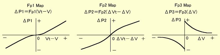
ΔP1 is a feedback control amount based upon
the difference in the magnitude between the target vehicle speed Vt and
the actual own vehicle speed V for the prime mover output to be increased
more as the difference is larger or to be decreased more as the difference
is larger in minus, so as to cancel the difference between Vt and V.
ΔP2 is a feedforward control amount based upon
the difference in the changing rate between the target vehicle speed Vt
and the actual own vehicle speed V for the prime mover output to be increased
more as the difference is larger or to be decreased more as the difference
is larger in minus, so as to compensate for a delaying or an advancing
tendency of the follow control.
ΔP3 is a control amount based upon the changing
rate of the actual own vehicle speed for the prime mover output to be increased
less as the changing rate is larger or to be decreased less as the changing
rate is larger in minus, so as to compensate for the number of crew member
or members and the mass of load as the vehicle becomes more reluctant to
change its speed according to changes of the prime mover output (and also
of the braking force) along with increase of its inertial mass.
Similarly, the braking force control to pursue
to accord each momentary V with each momentary Vt is made in each of the
cyclic control so as to modify each momentary braking force value B by
the below-mentioned increments or decrements ΔB1, ΔB2 and ΔB3:
ΔB1 is a functional value to vary as shown in "Fb1 Map" shown
hereinunder depending upon V-Vt, i.e. difference between V and Vt at each
moment:
ΔB1=Fb1(V-Vt)
ΔB2 is a functional value to vary as shown in "Fb2 Map" shown
hereinunder depending upon ΔV-ΔVt , i.e. difference between a momentary
difference ΔV of the current momentary own vehicle speed V(n) from the
momentary own vehicle speed V(n-1) at the preceding cycle and a momentary
difference ΔVt of the current momentary target vehicle speed Vt(n) from
the momentary target vehicle speed Vt(n-1) at the preceding cycle:
ΔB2=Fb2(ΔV-ΔVt)
ΔB3 is a functional value to vary as shown in "Fb3 Map" shown
hereinunder depending upon ΔV , i.e. difference of the current momentary
own vehicle speed V(n) from the momentary own vehicle speed V(n-1) at the
preceding cycle:
ΔB3=Fb3(ΔV)
ΔB1, ΔB2 and ΔB3 are to incorporate the feedback
control, the feedforward control and the effect of the inertial mass of
the vehicle into the control of the braking force for cancelling the difference
between Vt and V in the same manner as described above with respect to
ΔP1, ΔP2 and ΔP3.
The flow of the abovementioned control which is
started with the prime mover output control when "Vt>V" and continued
as concentrated thereto based upon ΔP1, ΔP2 and ΔP until the prime mover
output value P is reduced to 0, or started with the braking force control
when "Vt<V" and continued as concentrated thereto based upon
ΔB1, ΔB2 and ΔB3 until the braking force value B is reduced to 0, is as
shown hereinunder:
When the congestion follow control was optionally
put on by the driver (START), the target vehicle speed Vt is calculated
in step 10 based upon the inter-vehicles distance at that moment and compared
in step 20 with the vehicle speed V at that moment. Thereafter Vt is over
again compared with V by the control returning to step 10 and further proceeding
to step 20 as a series of the prime mover output control was finished,
or a series of the braking force control was finished.
When the prime mover output control has once been
started by the control proceeding to step 30, the control proceeds through
steps 40, 50, 60 and 70 so as to modify the value of P by Fp1(Vt-V)+Fp2(ΔVt-ΔV)+Fp3(ΔV),
and in step 80 judges if P has been returned to 0 or not, while repeating
steps 30-70 until P is returned to 0. This is the control executed
as concentrated to the prime mover output control based upon the judgment
of "Vt>V".
Similarly, when the braking force control
has once been started by the control proceeding to step 110, the control
proceeds through steps 120, 130, 140 and 150 so as to modify the value
of B by Fb1(V-Vt)+Fb2(ΔV-ΔVt)+Fb3(ΔV), and in step 160 judges if B has
been returned to 0 or not, while repeating steps 110-150 until B is returned
to 0. This is the control executed as concentrated to the braking
force control based upon the judgment of "V>Vt"
When it is neither "Vt>V" nor "V>Vt"
as the control returns to step 10, that is "Vt=V", and the vehicle
is running with Vt being not 0 so that the answer of step 102 is "no",
the control returns to step 10 through steps 100 and 102. When the
control circulates through steps 10, 20, 100 and 102 and the prime mover
is an internal combustion engine, there is effected the engine braking.
If at this time the vehicle is on a downhill and the engine braking
is suited to the inclination thereof, the control circulates through steps
10, 20, 100 and 102 with P and B being 0 (corresponding to the condition
that none of the accelerator pedal and the brake pedal is depressed). In
this case, if the automatic transmission is so adapted that the shift position
is automatically changed over D through L according to the inclination
of the road surface when it is a downward slope, the engine braking will
be available on the downhills as automatically most suitably adjusted in
relation to the congestion follow control.
On the other hand, when it is neither "Vt>V"
nor "V>Vt" as the control returns to step 10, that is "Vt=V",
and it is particularly Vt=V=0, the control proceeds to step 104 and the
braking force value B is set to Bo for the temporary stoppage.
When the congestion follow control is started,
the control circulates through the above control flow by a minute cycle
time such as several tens of milliseconds while executing either of the
above controls and successively modifies the driving/braking condition
of the vehicle so that the driving of the vehicle follows the above map
of "Inter-vehicles distance vs. Target vehicle speed".
By progressively modifying "inter-vehicles distance vs. Target vehicle
speed Map", "Fp1 Map", "Fp2 Map", "Fp3 Map",
"Fb1 Map", "Fb2 Map" and "Fb3 Map" so as
to attain even better settings thereof according to the accelerating and
braking performances of each vehicle of various models through experimental
drivings, the improvement of the follow-driving performane can be infinitely
pursued.
The measured values of the inter-vehicles distance and
the vehicle speed will be accompanied by the respective errors due to the
accuracy of the measuring means, but this will be of no problem for the
above control. When it is assumed, for example, that the vehicle
speed is measured 5% higher by the vehicle speed measuring means of the
own vehicle when it is following to a preceding vehiclle driven precisely
at a constant vehicle speed of 15km/h at the same constant vehicle speed,
the vehicle speed will be measured as 15.75km/h, so that the inter-vehicles
distance to follow the above map should be 4.82m. When at this time
the inter-vehicles distance measuring means measures the inter-vehicles
distance to be 7% less in such a region of inter-vehicles distance, 4.82m
is in fact a value measured for 5.16m. Therefore, after all the own
vehicle will follow the preceding vehicle driven precisely at the constant
vehicle speed of 15km/h at the same constant vehicle speed by taking the
inter-vehicles distance of 5.16m thereto.
The caculations around the above flowchart
may be carried out without cessation while this congestion follow control
is being put on, so that the prime mover or the brake system is operated
according to the result of the caculations as long as neither the accelerator
pedal nor the brake pedal is depressed, and when the accelerator pedal
or the brake pedal is depressed, the operation of the prime mover or the
brake system is assigned meantime to the operation of the accelerator pedal
or the brake pedal by an accelarator/brake operating system such as shown
below, and further, when the pedal depression has ended, the operation
of the prime mover or the brake system is returned to the control calculations maintained continuously while the accelerator pedal or the brake pedal is being operated.
Patent Claims
Claim 1
A vehicle drive control device in congestion
for controlling a prime mover and a brake system of a vehicle so as to
let the own vehicle proceed to follow a proceeding of a preceding vehicle,
wherein the device has a map prepared to correlate a target vehicle speed
for the own vehicle to an inter-vehicles distance between the preceding
vehicle and the own vehicle so that the target vehicle speed increases
gradually from zero as the inter-vehicles distance increases from a minimum
amount to be taken when the preceding vehicle and the own vehicle are both
in stoppage, and is adapted to control the output of the prime mover or
the braking force of the brake system so as to approximate the actual vehicle
speed of the own vehicle to the target vehicle speed corresponding to the
actual inter-vehicles distance detected,
wherein in the control for approximating
the actual vehicle speed to the target vehicle speed it is judged if the
target vehicle speed is larger than the actual vehicle speed, and when
it is judged that the target vehicle speed is larger than the actual vehicle
speed, the control for approximating the actual vehicle speed to the target
vehicle speed is started as a control of the prime mover output, whereas
when it is judged that the target vehicle speed is smaller than the actual
vehicle speed, the control for approximating the actual vehicle speed to
the target vehicle speed is started as a control of the braking force,
and
when the control for approximating the actual
vehicle speed to the target vehicle speed is started as the prime mover
output control by the target vehicle speed being judged as larger than
the actual vehicle speed, the braking force is once made zero, while when
it is judged that the target vehicle speed is neither larger nor smaller
than the actual vehicle speed, it is judged if the target vehicle speed
or the actual vehicle speed is zero, and when it is judged that the target
vehicle speed or the actual vehicle speed is zero, the braking force is
set to a braking force for stoppage.
Claim 2
A vehicle drive control device in congestion
for controlling a prime mover and a brake system of a vehicle so as to
let the own vehicle proceed to follow a proceeding of a preceding vehicle,
wherein the device has a map prepared to correlate a target vehicle speed
for the own vehicle to an inter-vehicles distance between the preceding
vehicle and the own vehicle so that the target vehicle speed increases
gradually from zero as the inter-vehicles distance increases from a minimum
amount to be taken when the preceding vehicle and the own vehicle are both
in stoppage, and is adapted to control the output of the prime mover or
the braking force of the brake system so as to approximate the actual vehicle
speed of the own vehicle to the target vehicle speed corresponding to the
actual inter-vehicles distance detected,
wherein the control for approximating the actual
vehicle speed to the target vehicle speed by the control of the prime mover
output is a control to modify the prime mover output at each cycle of control
cycles repeated with a minute cycle time by the sum of a first prime mover
output modification amount based upon a difference between the target vehicle
speed and the actual vehicle speed at the cycle, a second prime mover output
modification amount based upon a difference between a difference between
the target vehicle speed at the cycle and the target vehicle speed at a
cycle preceding the cycle and a difference between the actual vehicle speed
at the cycle and the actual vehicle speed at a cycle preceding the cycle,
and a third prime mover output modification amount based upon a difference
between the actual vehicle speed at the cycle and the actual vehicle speed
at a cycle preceding the cycle.
Claim 3
A vehicle drive control device in congestion
for controlling a prime mover and a brake system of a vehicle so as to
let the own vehicle proceed to follow a proceeding of a preceding vehicle,
wherein the device has a map prepared to correlate a target vehicle speed
for the own vehicle to an inter-vehicles distance between the preceding
vehicle and the own vehicle so that the target vehicle speed increases
gradually from zero as the inter-vehicles distance increases from a minimum
amount to be taken when the preceding vehicle and the own vehicle are both
in stoppage, and is adapted to control the output of the prime mover or
the braking force of the brake system so as to approximate the actual vehicle
speed of the own vehicle to the target vehicle speed corresponding to the
actual inter-vehicles distance detected,
wherein the control for approximating the actual
vehicle speed to the target vehicle speed by the control of the braking
force is a control to modify the braking force at each cycle of control
cycles repeated with a minute cycle time by the sum of a first braking
force modification amount based upon a difference between the actual vehicle
speed and the target vehicle speed at the cycle, a second braking force
modification amount based upon a difference between a difference between
the actual vehicle speed at the cycle and the actual vehicle speed at a
cycle preceding the cycle and a difference between the target vehicle speed
at the cycle and the target vehicle speed at a cycle preceding the cycle,
and a third braking force modification amount based upon a difference between
the actual vehicle speed at the cycle and the actual vehicle speed at a
cycle preceding the cycle.
Claim 4
A vehicle drive control device in congestion
according to any one of claims 1-3, wherein the control for approximating
the actual vehicle speed to the target vehicle speed is executed by a follow
proceeding switch to be changed over between ON and OFF by a driver being
made ON, and when either an accelerator pedal or a brake pedal is depressed
in the state that the follow proceeding switch is made ON, the control
of the prime mover or the brake system based upon a computed control amount
is intercepted so that a priority is placed on a control of the prime mover
or the brake system by the accelerator pedal or the brake pedal although
a computation of the control amount is continued.
Claim 5
A vehicle drive control device in congestion
according to any one of claims 1-4, wherein when the control for approximating
the actual vehicle speed to the target vehicle speed has been started as
the control of the prime mover output, the control is executed as the prime
mover output control regardless of the magnitude correlation between the
target vehicle speed and the actual vehicle speed until the prime mover
output is reduced to a minimum amount thereof, and when the prime mover
output has been reduced to the minimum amount, the magnitude correlation
between the target vehicle speed and the actual vehicle speed is judged
again, whereas when the control for approximating the actual vehicle speed
to the target vehicle speed has been started as the control of the braking
force, the control is executed as the braking force control regardless
of the magnitude correlation between the target vehicle speed and the actual
vehicle speed until the braking force is reduced to a minimum amount thereof,
and when the braking force has been reduced to the minimum amount, the
magnitude correlation between the target vehicle speed and the actual vehicle
speed is judged again, and subsequent to the re-judgement of the magnitude
correlation between the target vehicle speed and the actual behicle speed,
the control for approximating the actual vehicle speed to the target vehicle
speed is re-started as the prime mover output control when it is judged
that the target vehicle speed is larger than the actual vehicle speed,
whereas the control for approximating the actual vehicle speed to the target
vehicle speed is re-started as the braking force control when it is judged
that the target vehicle speed is smaller than the actual vehicle speed.
Return to the top
Vehicle to make use of inertial running for ecomomic driving
It is guessed that most drivers are driving the
current automatic automobiles on the flat road by depressing the accelerator
pedal or the brake pedal alternatively to start, accelerate, decelerate
or temporarily stop the vehicle with the shift lever being kept as shifted
to the D range position. Since a fluid torque converter is interposed
between the engine and the speed change gear in the automatic automobiles,
even when the vehicle is stopped by a depression of the brake pedal with
the shift lever being shifted to the D range position which puts a cluch
provided at the entrance of the speed change gear into engagement so as
to establish the driving connection between the engine and the wheels,
the engine can continue its rotational operation without causing the engine
stall or stop by the slipping allowance available by the fluid torque converter.
By such an incorporation of the fluid torque converter in the drive
system and the automatic changeover of the gear ratios of the speed change
gear according to the driving conditions of the vehicle, the automobile
driving on the flat road is now free to start, accelerate, decelerate or
temporarily stop the vehicle only by the alternative depression of the
accelerator pedal and the brake pedal with the shift lever being kept as
shifted to the D range position.
The rotational speed of the wheels changes
according to the vehicle speed so as to be higher as the vehicle speed
is higher. The rotational speed of the engine changes according to
the depth of depression of the accelerator pedal so as to be higher as
the depression of the accelerator pedal is deeper. Therefore, when
the vehicle is being driven in the D range which drivingly connects the
engine with the wheels, the vehicle is in either of such conditions according
to the relative correlation in magnitude between the vehicle speed and
the depression of the accelerator pedal that the engine drives the wheels,
the engine is reversely driven by the wheels, and a condition intermediate
therebetween wherein neither the engine nor the wheels drive the other.
When the accelerator pedal is depressed to
some certain depth with the shift lever being shifted to drive range positions
such as D, 2 and L positions, the wheels are driven by the engine so that
the vehicle is in the normal driving condition.
When the accelerator pedal is released, the
supply of the fuel to the engine is throttled to a minimum rate necessary
to maintain the engine in the operational condition, so that the engine
would rotate at a very low idling speed. However, when at that time
the vehicle is running at a speed higher than a certain speed with the
shift lever being shifted to a drive range position such as D, 2 or L position,
it occurs that the engine is reversely driven by the wheels so as to rotate
at a speed higher than the idling speed due to the running inertia of the
vehicle even though the abovementioned fluid torque converter is provided.
In this condition the engine operates to suppress the inertial running
of the vehicle such that the vehicle is braked even though the brake pedal
is not depressed. This is the so-called "engine braking"which
itself is beneficial from the view point of the driving stability of the
vehicle and essential to prevent the overheating of the brake pad in descending
the slope. However, it shortens the distance of inertial running
of the vehicle on the flat road as compared with that available by the
inertial running with no engine braking.
Now, there are a lot of scenes in the driving
of the vehicle that the vehicle may be left to run only by the inertia.
For example, it happens that the traffic signal which newly appeared
in the front view is red or has just changed to red, so that it is certain
that the vehicle is soon forced to temorarily stop, and therefore may slowly
arrive at a position somewhat short of the signal with no hurry. In
such a case, although it is possible to save the fuel by letting the vehicle
run by inertia while releasing the accelerator pedal at an early stage
so that the vehicle will come to stoppage with as less braking as possible,
it is still further possible to save more fuel if it is so adjusted that
no engine braking is effected in the inertial running so that the distance
of the inertial running is elongated and therefore the accelerator pedal
may be released at an earlier stage to save more fuel. As another
scene, when the vehicle will descend a very moderate slope at a constant
speed by the inertial running while just overcoming the resistances from
the air and the road surface if no engine braking is effected, the fuel
can be saved so far by so adapting that the engine braking is optionally
cancelled as desired. There are other such scenes in the vehicle
driving that the vehicle need not be further accelerated or may slow down
more or less, so that the driver is unwilling to depress the accelerator
pedal, but it is too much to tolerate that the vehicle is decelerated by
the engine braking by the accelerator pedal being released, suggesting
a desirable condition that neither acceleration nor braking is effected.
If the vehicle is so adapted that the engine
braking can be easily cancelled when the inertial running is desired or
allowed, it is possible to make use of the inertial running much more in
the vehicle driving, so that even if the vehicle becomes heavier by being
constructed to be stronger, the energy of the additional fuel required
for accelerating the additional mass of the vehicle increased by constructing
the vehicle stronger is stored as the inertial energy of the vehicle which
can be recovered as the increase of the inertial running distance of the
vehicle to be able to run against the resistances from the air and the
road surface, whereby the vehicles can be constructed to be more safe against the collision accidents
without sacrificing the fuel consumption performance. It is the matter that is known by those who really know the matter
how much crucial the strength of the vehicle body is to the damage suffered
by the human body in the collision accidents, as there are those who purposely
select the Benz for self-defense.
Since as described above the clutch is provided
at the entrance of the speed change gear for its selective connection with
the engine, and since the clutch is disengaged when the shift lever is
shited to the N range position, the driver is only required to shift the
shift lever to the N range position each time when he or she desires to
cancel the engine braking in the inertial running. However, such
an action is troublesome and spoils the merit of the automatic vehicle
that it attains every running condition ranging from start to temporary
stop through acceleration and deceleration only by the alternative depression
of the accelerator pedal and the brake pedal when the shift lever has once
been shifted to the D range position.
Thus it is herein proposed to make it possible
to cancel the engine braking by a minute operation of the accelerator pedal
with no need of manipulation of the shift lever.
The automatic vehicle is provided with such
a variable speed drive system as shown hereinunder, provided that the solenoid
changeover valve 30 is not provided, ie. added by the present invention,
so that conventionally the oli pressure supply line 38 is directly connected
to the oil pressure inlet port 18 of the range changeover valve 16. According
to the present invention the newly added solenoid changeover valve 30 is
operated to cancel the engine braking in response to a minute depression
δ of the accelerator pedal 48 from its return position only when the vehicle
is running at a speed higher than a certain slowdown speed.
In the automatic vehicle the wheels are driven
by the engine 10 via the speed change gear 12 including the clutch 14 provided
at the entrance thereof as shown in the above figure. Further, although
not shown in the figure, a fluid torque converter is interposed between
the engine 10 and the speed change gear 12, so that even when the vehicle
is stopped by a depression of the brake pedal with the shift lever being
shifted to the D range position, ie. the clutch 14 being in engagement,
the engine can continue to rotate as allowed by a slipping rotation of
the fluid torque converter.
The speed change gear 12 incorporates therein
a speed change gear mechanism for changing over the transmission ratio
among several values, and is so adapted that when the range changeover
valve 16 is shifted to either of the D-L range positions, the oil pressure
supplied to the oil pressure inlet port 18 is delivered to the oil pressure
outlet port 20 so as to be supplied to and engage the clutch 14, so that
the rotation inputted from the engine through the abovementioned fluid
torque converte is changed over among various speed ratios according to
the relative conditions between the accelerator pedal depression and the
vehicle speed to accomplish proper speed stages ranging from the lowest
speed stage to the highest speed stage. And further, when the range
changeover valve 16 is shited to the 3, 2 or L range position, the speed
change gear is compulsoriky shifted down to the 3, 2 or 1 speed stage by
the oil pressure successively additionally delivered to the oil pressure
outlet ports 22, 24 and 26.
In the current conventional automatic vehicles
the oil pressure inlet port 18 is supplied with the oil pressure directly
from the oil pressure supply line 38. When the range changeover valve
16 is set to the N position as shown in the figure, the oil pressure supplied
to the oil pressure inlet port 18 is not delivered to the oil pressure
outlet port 20, so that the clutch 14 is being disengaged. When the
range changeover valve 16 is shifted to either of the D-L positions, the
clutch 14 is supplied with the oil pressure and engaged.
Thus, when it is so adapted that the solenoid
changeover valve 30 is provided in the way of the oil passage leading from
the oil pressure supply line 38 to the oil pressure inlet port 18 so as
normally to be in the state shown in the figure to connect the oil pressure
inlet port 18 with the oil pressure supply line 38 but temporarily to disconnect
the oil pressure inlet port 18 from the oil pressure supply line 38 and
instead to connect it to the drain port 39 by the solenoid changeover valve
30 being shifted leftward in the figure by energization of its solenoid
36 when the vehicle is running at a speed higher than a predetermined slowdown
speed in the D range and the accelerator pedal is depressed from the return
position as much as the minute depth δ so as to be detected by the senser
46 to effect the energization of the solenoid 36 by way of the central
processingl unit 40, the vehicle can be readily put into inerial running
with no engine braking being effected by disengaging the clutch 14 by a
minute depression of the accelerator pedal, with no need of shifting the
shift lever to the N position, in such an occasion that the traffic signal
which newly appeared in the front view is red or has just changed to red,
so that it is certain that the vehicle is soon forced to temorarily stop,
and therefore may slowly arrive at a position somewhat short of the signal
with no hurry, the vehicle is desired to descend a very moderate slope
at a constant speed while just overcoming the resistances from the air
and the road surface with no engine braking being effected, or the vehicle
need not be further accelerated or may slow down more or less, so that
the driver is unwilling to depress the accelerator pedal, but it is too
much to tolerate that the vehicle is decelerated by the engine braking
by the accelerator pedal being released, suggesting a desirable condition
that neither acceleration nor braking is effected.
The flow of control is as follows:
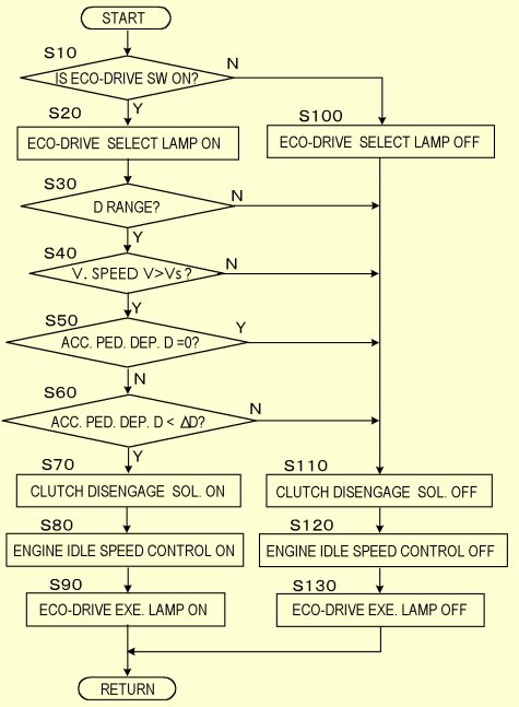
The abovementioned minute depression δ(<ΔD)
is of such a depth that the driver clearly recognizes that he or she has
certainly depressed the accelerator pedal from the return position within
a range that is smaller than the depth to let the vehicle run at a constant
speed by just overcoming the resistances from the air and the road surface.
In summary, the operations are as follows:
(1) Since the engine braking is effected as usual when the accelertor
pedal is returned to the return position, the conventional drive feeling
that the engine braking is effected when the accelerator pedal is released
is ensured.
(2) When the vehicle is started from the standstill state, the
accelerator pedal will be depressed from the return position to a certain
depth enough to move the vehicle by overcoming the large inertia of the
whole mass of the vehicle accross the abovementione δ with one push before
the vehicle attains the slowdown speed, while it is only when the vehicle
is running at a speed higher than the slowdown speed that the clutch is
disengaged by a minute depression of the accelerator pedal, and therefore,
it never occurs that the clutch is disengaged in the way of depressing
the accelerator pedal in the start of the vehicle, that is, it never occurs
that the acceleration in the starting from the standstill state breathes
due to an unexpected temporary disengagement of the clutch.
(3) Since it is limited to the state that the vehicle is running
at a speed higher than the slowdown speed that the clutch is disengaged
by a minute depression of the accelerator pedal, it never occurs that the
clutch is disengaged by the accelerator pedal being depressed to a small
depth including the abovementioned δ in such a very slow driving as met
in parking the vehicle in a garage.
(4) Since the vehicle receives the resistances from the air
and the road surface even on a paved road due to the tire deformation in
its running, the accelerator pedal is depressed beyond a certain depth
enough to cancel such resistances in order for the vehicle to run at a
constant speed higher than the slowdown speed. Therefore, when the
abovementioned δ is set within a range smaller than the depth of depression
to let the vehicle run at a speed higher than the slowdown speed by cancelling
the resistances from the air and the road surface, it never occurs that
the clutch is disengaged when the vehicle is running at a speed higher
than the slowdown speed.
(5) When the vehicle may be decelerated more or less by
the resistances from the air and the road surface, while there is no need
for the engine braking to act, so that the vehicle is desired to run as
much as possible by the inertia of the vehicle after it has once been accelerated
above the slowdown speed, the clutch of the speed change gear is disengaged
not to effect the engine braking only by a minute depression of the accelerator
pedal with no need of shifting the shift lever to the N position, so as
thereby to let the vehicle run by exhibiting its inertial running ability
to its extremity.
Still, it may be only when the driver has
optionally pressed the eco-driving button 50, requiring such an operation
that the clutch is disengaged by a minute depression of the accelerator
pedal.
Patent Claims
Claim 1
A vehicle with wheels adapted to be driven
by an internal combustion engine via an automatic transmission, the automatic
transmission including a main clutch to be engaged when the automatic transmission
is set to the D-range and to dissolve the driving connection between the
internal combustion engine and the wheels when disengaged, wherein when
an accelerator pedal is depressed by a driver within a predetermined minute
range when the vehicle is running at a vehicle speed higher than a so-called
slow drive speed with the automatic transmission being set to the D-range,
the main clutch is disengaged, the predetermined minute range being such
that is perceived by the driver as distinctly depressed from its return
end position but less than a depth of depression to let the vehicle run
at a constant vehicle speed higher than the so-called slow drive speed
by conquering the air resistance and the tire deformation resistance.
Claim 2
A vehicle according to claim 1, wherein when
the main clutch is disengaged by the accelerator pedal being depressed
from the return end position within the predetermined minute range when
the vehicle is running at a vehicle speed higher than the so-called slow
drive speed with the automatic transmission being set to the D-range, the
internal combustion engine is controlled of its idling speed in accordance
with the speed of the vehicle.
Claim 3
A vehicle according to claim 1 or 2, wherein
it is when an eco-drive switch optionally manipulated by the driver is
made ON that the main clutch is disengaged by the accelerator pedal being
depressed from the return end position within the predetermined minute
range when the vehicle is running at a vehicle speed higher than the so-called
slow drive speed with the automatic transmission being set to the D-range.
Claim 4
A vehicle according to claim 3, wherein an
eco-drive select indicator is provided to show the driver that the eco-drive
switch is made ON.
Claim 5
A vehicle according to any one of claims
1-4, wherein an eco-drive execution indicator is provided to show the driver
that the main clutch is disengaged by the accelerator pedal being depressed
from the return end position within the predetermined minute range when
the vehicle is running at a vehicle speed higher than the so-called slow
drive speed with the automatic transmission being set to the D-range.
Return to the top
Carrier for persons unable to walk
Nowadays the persons who are unable to walk
by themselves have increased, with an incidental increase of those who
are unable even to transfer from the bed to the wheelchair or vice versa
by themselves, raising a new problem that the care givers who must embrace
the care receivers to transfer them between the beds and the wheelchairs
suffer the waist pain. Further, the care for the evacuation in the nursing
care is imposing a particularly serious load on the care givers.
Proposed herein is a carrier which not only enebles
the care giver easily to transfer the care receiver between the bed and the wheelchair by oneself alone with no need for the care giver to bow or embrace the care receiver while
keeping the care receiver in the sitting posture, but also enables that
the care receiver is scooped up in the sitting posture to be transferred
to the toilet, placed on the lavatory seat of the western style lavatory
pot in the relieving mode, allowed to relieve, and transferred back from
the toilet to the bed in the same posture. Since the western style
lavatory pots are nowadays widely equipped with the fountain device for
cleaning the anal area, the care receivers disabled in the waist or legs
can thus enjoy a comfortable relieving in the lavatory, not on the portable
pot, while the care givers are liberated from wiping the bottom of the
care receivers..
The care giver can carry the care receiver
as sitting on the seat plate to face the care giver who depresses the pedal plate with his/her one foot to balance the weight of
the care receiver with his/her own weight, while kicking the floor by his/her other foot for driving the carrier.
When the caster is so designed as to extend properly around the central
post, the carrier will stand with a certain own stability that allows for
a relatively large difference between the weight of the care receiver applied
to the seat plate and the weight of the care giver applied to the pedal
plate. Further, although not shown in the figure, a temporary support
leg may be provided so as to be optionally turned down from the rotatable
frame so that the care giver is allowed to release the depression of the
pedal plate when desired.
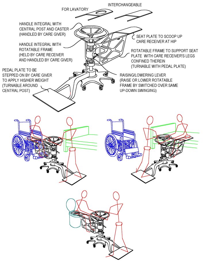
Patent Claims
Claim 1
A carrier for persons unable to walk, comprising
a base freely movable on a floor in optional directions therealong by a
plurality of casters, a post supported vertically by the base, and a rotatable
frame supported by the post to be freely rotatable therearound and to extend
on opposite sides thereof, wherein a seat plate is mounted to an extending
end of the rotatable frame to let a care receiver sit thereon as facing
the post, and a pedal plate is mounted to another extending end of the
rotatable frame to let a care giver apply his/her own weight thereto by
a depression thereof by his/her foot.
Claim 2
A carrier according to claim 1, wherein the
rotatable frame has a pair of horizontal tubular arms at the end for mounting
the seat plate, and the seat plate has a pair of supporting rods extending
from opposite sides thereof of an end portion thereof facing the arms of
the rotatable frame to be inserted into the tubular arms, so that the seat
plate is removably mounted to the rotatable frame by an insertion of the
supporting rods into the tubular arms.
Claim 3
A carrier according to claim 1 or 2, wherein
the seat plate is planted with bristles in at least one of upper and lower
surfaces thereof to decrease the sliding resistance of the seat plate against
an article to slide in contact therewith by the bristles being bent to
incline in the direction of the relative movement between the seat plate
and the article.
Claim 4
A carrier according to claim 1, 2 or 3, wherein
the seat plate is prepared in plurality so that they are exchangeably mounted
to the rotatable frame.
Claim 5
A carrier according to claim 4, wherein at
least one of the plurality of seat plates is formed with an opening at
a central portion thereof to match with an inside edge of the lavatory
seat of the western style lavatory pot, so that the care receiver can relieve
as seated on the seat plate.
Claim 6
A carrier according to any one of claims
1-5, wherein the rotatable frame is provided with an annular handle for
rotating the rotatable frame around the post.
Claim 7
A carrier accordong to any one of claims
1-6, wherein the post is provided with an annular handle concentric to
a central axis thereoof.
Claim 8
A carrier according to any one of claims
1-7, wherein an oil-hydraulic cylinder/piston device by a piston fastened
to the post and a cylinder fastened to the rotatable frame is provided
so as to support the rotatable frame by the post to be freely rotatable
therearound while a height of the support of the rotatable frame by the
post is adjustable within a certain range, and the height of the support
is adjusted by an amount of oil being transferred between an upper cylinder
chamber and a lower cylinder chamber formed in the cylinder as separated
by the piston.
Claim 9
A carrier according to claim 8, wherein a
pump is provided by a construction that a pump plate is reciprocatingly
inclined around a rotary axis located at a pivot of a sector-shaped pump
chamber as a means for transferring the oil between the upper and lower
cylinder chambers, the pump plate being provided with first and second
non-return valves parallel with one another adapted such that the first
non-return valve allows the oil to flow only from one side thereof to another
side thereof while the second non-return valve allows the oil to flow only
from the other side to the one side, the pump further comprising a pumping
direction changeover means adapted to be changed over between a first changeover
position to make the first non-return valve operable while intercepting
the second non-return valve and a second changeover position to make the
second non-return valve operable while intercepting the first non-return
valve.
Claim10
A carrier according to claim 8 or 9, wherein
the pump is adapted to close a port for connecting the sector-shaped pump
chamber with the upper or lower cylinder chamber when it is in at least
one position of the reciprocatingly inclining movement.
Return to the top
Rotatable tray for dining
When the foods are served to the patient
or the older person in the hospital or the nursing home as arranged on
a tray, the food located at a remoter back position is apt to be left as
uneaten. If the tray can be easily rotated, it will be optionally
rotated in the course of dining so that each food to eat is brought to
the front position for easier eating and not to be spilled, while leaving
no food as uneaten.
However, the rotatable tray for such a purpose
should satisfy such conditions as listed below:
(1) Can be easily and cleanly washed by water after each service.
(2) Be such a light construction as to be held by the hand for water
washing without much loading the hand.
(3) Be insensitive to the pollution by foods so as not to cause troubles
in the rotating mechanism.
(4) Can be lightly and extensively rotated by a small movement of
the hand and still be stable at any rotational position.
(5) Be not expensive.
A rotatable tray assembled from a tray plate, a bearing plate and a base plate as shown hereinunder is herein proposed to satisfy the abovementioned conditions:
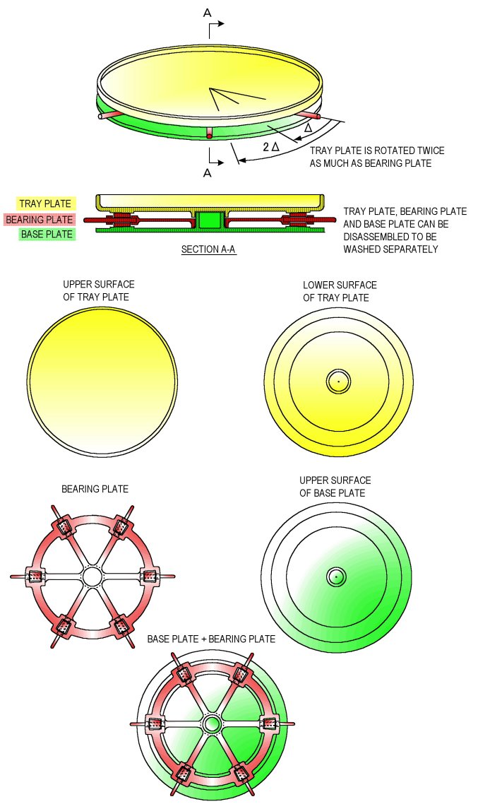
Patent Claims
Claim 1
A rotatable tray for dining comprising a
base plate, a bearing plate and a tray plate laid one over the other in
contact with one another so as to be rotatable relative to one another
around a common central rotation axis and removable from one another along
the central rotation axis, the bearing plate having at least three rollers
and a roller support frame to support the rollers each to be rotatable
around each of roller rotation axes extending radially from the central
rotation axis, the roller supprt frame having handles projecting out of
outer peripheries of the base plate and the tray plate, wherein the rollers
are each adapted to roll around each of the roller rotation axes in contact
with an upper surface of the base plate and a lower surface of the tray
plate when the tray plate is rotated relative to the base plate around
the central rotation axis, the tray plate being rotated relative to the
base plate twice as much as an angle of rotation of the roller support
frame relative to the base plate when the roller support frame is rotated
around the central rotation axis relative to the base plate by the handles.
Claim 2
A rotatable tray for dining according to
claim 1, wherein the rollers are each a tapered roller having an inside
radius at an inside end thereof closer to the central rotation axis and
an outside radius different from the inside radius at an outside end thereof
remoter from the central rotation axis each along the roller rotation axis,
the ratio of the outside radius to the inside radius being equal to the
ratio of the distance of the outside end from the central rotation axis
to the distance of the inside end from the central rotation axis, and the
upper surface of the base plate and the lower surface of the tray plate
are respectively provided with annular belt regions at portions thereof
contacting with the rollers each being inclined to meet with tapered peripheral
surfaces of the tapered rollers.
Claim 3
A rotatable tray for dining according to
claim 1 or 2, wherein the roller support frame has a central bearing portin
for engaging with the base plate to be rotatable relative thereto around
the central rotation axis, a plurality of roller bearing portions each
supporting each of the rollers to be rotatable therearound, an annular
frame portion connecting the plurality of roller bearing portions with
one another, and a radial frame portion connecting each of the plurality
of roller bearing portions with the central bearing portion.
Claim 4
A rotatable tray for dining according to
any one of claims 1-3, wherein the handles are each an extension of a shaft
supporting each of the rollers to be rotatable therearound.
Return to the top
Tableware washer with brush rotatable by faucet water pressure
The water at the faucet of the waterworks
is applied with a substantial pressure which is not a dynamic pressure
due to the flowing momentum of water but is a static pressure workable
even in a very mild flow of water and therefore highly valuable as an energy
source. When the tableware is washed by the water from the faucet,
the water should not merely be splashed against the objects but also drive
a cleaning brush by utilizing the energy of the static water pressure contained
therein. Proposed hereinunder is such a tableware washer:
The device adapted to be mounted to the faucet
as to receive it in the inlet port 26 and fastened there by the screws
40 is constructed of a cylindrical housing 16 and a rotary piston 10 which
reciprocates in rotation in the housing 16 around the center line C-C as
illustrated hereinunder left in a longitudinal section. When the
rotary piston 10 is removed therefrom, the housing 16 alone looks as shown
hereinunder right.
When viewed in a section turned around the
center line C-C to be at right angle to the upper right view, the housing
16 looks as shown hereinunder.
When viewed downward by a horizontal section shown by IV-IV in the first shown view, it looks as shown hereinunder. Fig. (A) shows a state that the rotary piston 10 is at the end of clockwise rotation as viewed from the top, while Fig. (B) shows a state that the rotary piston 10 is at the end of anticlockwise rotation as viewed from the top.
The rotary piston 10 is as shown hereinunder,
wherein the left side view is a side view and the middle view is a plan
view. The housing 16 has a bottom wall 50 formed with a number of
holes 52 as shown in a bottom view hereinunder right.
The bottom wall 50 of the housing is covered
by a circular nozzle plate 54 as shown hereinunder to be rotatable so as
to adjust the opening rate of the holes 52 by the extent of overlapping
with the holes 56, as shown at the left side in the fully opened state,
and at the right side in the fully closed state.
Upon the mounting of the device shown above
to the faucet by the screws 40, when water only is desired, it flows out
through the female splined bore 60 opened through the central portion of
the rotary piston 10 in the same manner as flowing out directly from the
faucet, while when the energy of the static pressure of water is to be
effectively utilized for washing the tableware, the brush 66 or 78 is mounted
to the rotary piston 10 at its shaft portion with the male splined portion
62 thereof being engaged into the female splined bore 60.
When the male splined portion 62 of the brush
is inserted into the female splined bore 60 of the rotary piston 10, the
female splined bore 60 is blocked by the male splined portion 62, whereby
the water flows into the annular cylinder chambers 42a, 42b through the
inlet ports 28a, 28b so as to rotate the rotary piston 10, while the water
which has flowed into the annular cylinder chambers 42a, 42b in the preceding
cycle flows out therefrom through the outlet ports 32a, 32b so as to flow
into the annular channel 46 to be finally ejected from the openings 56
around the brush as splashed.
The supply of water into the annular cylinder
chambers 42a, 42b through the inlet ports 28a, 28b is changed over every
time when the changeover valves 36a, 36b provided in the intet ports 28a,
28b are reversed by being knocked by the drive pins 44aa, 44ab, 44ba, 44bb
according to the rotary movement of the rotary piston 10.
In more detail, when the operation is started
from the state that the rotary piston 10 is positioned as shown in the
figure of the above third rank left, wherein the changeover valve 36a is
changed over to the position shown in the figure of the above first rank
right as knocked by the drive pin 44aa, while the changeover valve 36b
is changed over to the position opposite to that of the changeover valve
36a as knocked by the drive pin 44bb, so that the water from the inlet
port 28a is changed over by the changeover valve 36a to be introduced into
the space on the right side of the plate portion 14a of the rotary piston
as viewed in the figure of the above third rank left, while the water from
the inlet port 28b is changed over by the changeover valve 36b to be introduced
into the space on the left side of the plate portion 14b of the rotary
piston as viewed in the figure of the above third rank left. Therefore,
the rotary piston is driven to rotate from the position shown in the figure
of the above third rank left anticlockwise until the drive pin 44ba thereof
strikes agains the changeover valve 36a as shown in the figure of the above
third rank right so as to change over the inclination of the changeover
valve 36a to be finally inclined as shown by the phantom lines in figure
of the above first rank right. Simultaneously, the changeover valve
36b is changed over by the drive pin 44ab from the position shown in the
figure of the above third rank left to the position shown in the figure
of the above third rank right.
Then next, the water from the inlet port
28a is guided by the changeover valve 36a to be introduced into the space
at the left side of the plate portion 14b of the rotary piston as viewed
in the figure of the above third rank right, while the water from the inlet
port 28b is guided by the changeover valve 36b to be introduced into the
space at the right side of the plate portion 14a of the rotary piston as
viewed in the figure of the above third rank right, whereby the rotary
piston is driven to rotate clockwise as viewed in the figure of the above
third rank right until it comes to the position shown in the figure of
the above third rank left.
In such a manner the rotary piston 10 reciprocates
in rotation to alternately repeat clockwise and anticlockwise half rotations
by driving the brush correspondingly, while the water which has driven
the brush is ejected from the holes 52 of the bottom wall of the housing
around the brush as optionally throttled by the nozzle plate 54.
Patent Claims
Claim 1
A tableware washer comprising a rotary piston
having a cylindrical portion and plate portions projecting radially from
an outer surface of the cylindrical portion, and
a housing having a bearing portion for supporting
the rotary piston to be rotatable around a central axis of the cylindrical
portion and an annular wall portion presenting an annular inside wall surface
for slidably contacting with edges of the plate portions of the rotary
piston when the rotary piston rotates around the central axis as supported
by the bearing portion,
wherein the rotary piston and the housing
are adapted to form an annular cylinder chamber therebetween when the rotary
piston is supported by the bearing portion of the housing to be rotatable
around the central axis with the plate portions of the rotary piston traversing
the annular cylinder chamber so as to separate the annular cylinder chamber
into a cylinder chamber space located on one side of the plate portions
and a cylinder chamber space located on another side of the plate portions,
the housing has further a water supply structure
having a bore for insertion of a faucet of the water supply system and
water supply ports for conducting water received from the faucet inserted
into the bore toward the annuar cylinder chamber, a water discharge structure
having water discharge ports for discharging water from the annular cylinder
chamber, and changeover valves for changing over flows of water flowing
from the water supply ports to the water dischage ports through the annular
cylinder chamber, the changeover valves being adapted to be changed over
between a first changeover position to connect the water supply ports to
a portion of the annular cylinder chamber extending on one side of the
changeover valves and disconnect the water supply ports from a portion
of the annular cylinder chamber extending on another side of the changeover
valves while connecting the water discharge ports to the portion of the
annular cylinder chamber extending on the other side of the changeover
valves and disconnecting the water discharge ports from the portion of
the annular cylinder chamber extending on the one side of the changeover
valves and a second changeover position to connect the water supply ports
to the portion of the annular cylinder chamber extending on the other side
of the changeover valves and disconnect the water supply ports from the
portion of the annular cylinder chamber extending on the one side of the
changeover valves while connecting the water discharge ports to the portion
of the annular cylinder chamber extending on the one side of the changeover
valves and disconnecting the water discharge ports from the portion of
the annular cylinder chamber extending on the other side of the changeover
valves ,
the rotary piston has a changeover valve
driving means to drive the changeover valves to the first changeover position
when the plate portions reach respective end positions of rotation in one
direction along the annular cylinder chamber and drive the changeover valves
to the second changeover position when the plate portions reach respective
end positions of rotation in another direction along the annular cylinder
chamber, and
the cylindrical portion of the rotary piston
is adapted to support a brush as removably inserted therein at one end
portion thereof so as to block an inside space of the cylindrical portion
and to rotate with the rotary piston.
Claim 2
A tableware washer according to claim 1,
wherein the plate portions of the rotary piston are provided in plurality
as equally spaced around the central axis of the cylindrical portion, while
the water supply ports, the water discharge ports and the changeover valves
are provided in the same plurality as similarly equally spaced.
Claim 3
A tableware washer according to claim 1 or 2, wherein the water discharge structure has further an annular water passage extending annularly along the annular cylinder chamber in connection with the water discharge ports, and a plurality of water ejection holes spaced along the annular water passage for ejecting water from the annular water passage.
Claim 4
A tableware washer according to claim 3,
wherein the water discharge structure has further a means for adjusting
an extent of opening of the water ejection holes between a fully opened
state and a fully closed state.
Retun to the top
Strap adjustable for height
Someone is tall and someone is short in the
world. These years the straps of the trains appear to have been arranged
such that those located in the doorway area are somewhat higher than those
located along the seats, probably for those located in the doorway not
to touch the heads of the tall passengers. In any event, the tall
passengers will sometimes stand in fron of the seats, while the short passengers
will sometimes stand in the doorway. Therefore, the straps are sometimes
too low and sometimes too high for the passengers. The straps should
be adjustable on the spot instantly and easily at least between two options
of height.
Herein is proposed a strap to meet with such
requirements:

Patent Claim
Claim 1
A strap comprising a suspending member equipped
with an annular grip supporter at a lower end thereof, and a rectangularly
annular grip threaded through an annulus of the grip supporter, the grip
being formed with indents complementary to a chain of four mountains contouring
the curves of insides of forefinger, second finger, third finger and little
finger of human at a central inside portion of each of the four sides of
the rectangular shape thereof, while the annulus of the grip supporter
is formed with a wavy portion complementary to the indents of the inside
surface of the grip, so as thereby to present a grip position suitable
to a short or a tall person according to whether the grip is used in a
vertically elongated posture or a horizontally elongated posture.
Return to the top
Ice cream container with cap attachable to bottom of cup
The cap removed from the cup of the ice cream
container to eat the ice cream becomes a useless object desirably to be
disposed with. When the ice cream is eaten at the table or on the
bench of the park where a garbage can is provided, there would be no problem.
Otherewise, however, the cap would be carelessly thrown away, or
even when it was intended to be disposed with after the ice cream has been
eaten, it might happen that the cap is left as forgotten, thereby causing
a pollution of the environment. Further, the cup of the ice cream
container made of paper or a thin sheet of synthetic resin is totally soft
and liable to deformation even when it is formed with a bead along its
open edge or reinforced at its bottom circumference by the circumferential
edge portion of the bottom wall being connected therewith, and not easy
to hold, particularly when the content has decreased. Further, since
the cup made of paper or a thin sheet of synthetic resin is poor in the
adiabaticity, when it is directly held by the fingers, the fingers are
cooled unpleasantly, while the ice cream in the cup is molten by the heat
transmitted from the fingers.
Herein is proposed an ice cream container
which allows the cap removed from the cup to be properly disposed with,
while allowing the user to eat the ice cream more pleasantly.
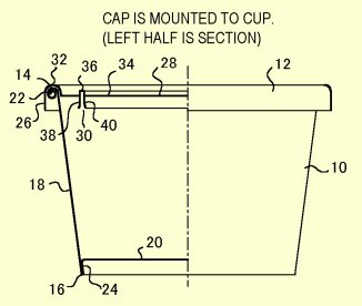
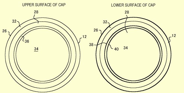
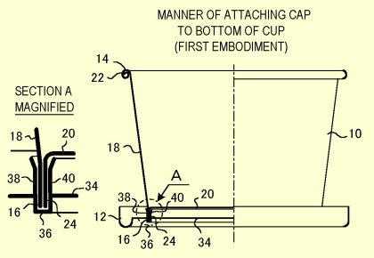
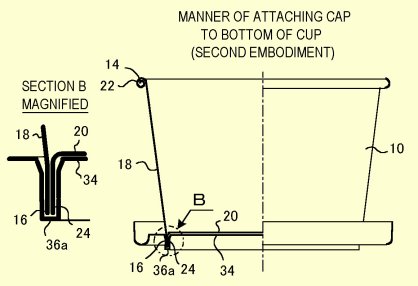
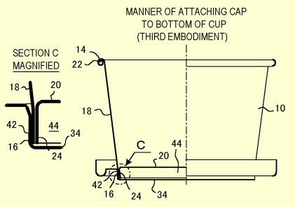
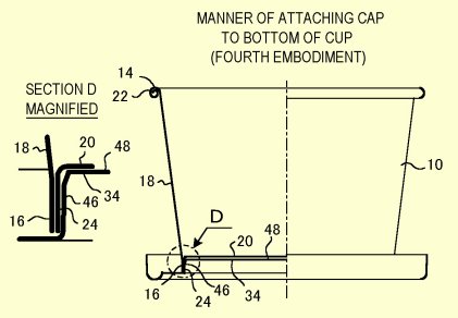
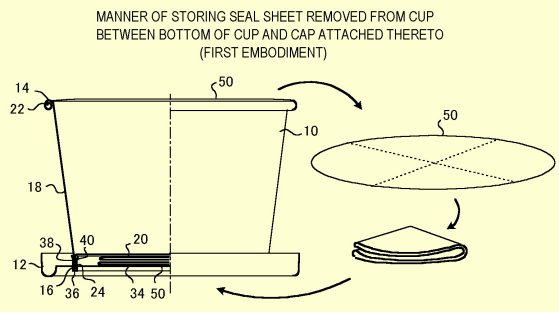
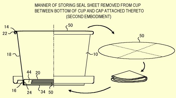
Patent Claims
Claim 1
An ice cream container comprising an assembly
of a cup having an annular side wall of a shape of inverse truncated cone
contracting from an annular upper edge fringing an open end thereof toward
an annular lower edge thereof and a bottom wall extending at a bottom portion
of the side wall, and a cap for closing the open end of the cup, wherein
the cap is formed with an annular contact face at an inside thereof adapted
to engage with a lower end portion of the annular side wall of the cup
for binding the cap with the cup by a friction engagement therebetween,
the bottom wall being shifted from the lower edge of the side wall toward
the upper edge thereof, and the annular contact face of the cap being two
annular faces adapted to contact with the lower end portion of the side
wall of the cup located below the bottom wall at both of the outside and
inside thereof.
Claim 2
An ice cream container comprising an assembly
of a cup having an annular side wall of a shape of inverse truncated cone
contracting from an annular upper edge fringing an open end thereof toward
an annular lower edge thereof and a bottom wall extending at a bottom portion
of the side wall, and a cap for closing the open end of the cup, wherein
the cap is formed with an annular contact face at an inside thereof adapted
to engage with a lower end portion of the annular side wall of the cup
for binding the cap with the cup by a friction engagement therebetween,
the bottom wall being shifted from the lower edge of the side wall toward
the upper edge thereof, and the annular contact face of the cap being an
annular face adapted to contact with the lower end portion of the side
wall of the cup located below the bottom wall at the outside thereof.
Claim 3
An ice cream container comprising an assembly
of a cup having an annular side wall of a shape of inverse truncated cone
contracting from an annular upper edge fringing an open end thereof toward
an annular lower edge thereof and a bottom wall extending at a bottom portion
of the side wall, and a cap for closing the open end of the cup, wherein
the cap is formed with an annular contact face at an inside thereof adapted
to engage with a lower end portion of the annular side wall of the cup
for binding the cap with the cup by a friction engagement therebetween,
the bottom wall being shifted from the lower edge of the side wall toward
the upper edge thereof, and the annular contact face of the cap being an
annular face adapted to contact with the lower end portion of the side
wall of the cup located below the bottom wall at the inside thereof.
Claim 4
An ice cream container according to any one
of claims 1-3, wherein a portion of the cap located at the inside of the
annular contact face is so adapted as to leave a space against the bottom
wall of the cup for storing a sheet sealing the open end of the cup as
removed therefrom and folded when the lower end portion of the side wall
of the cup is engaged with the annular contact face of the cap.
Return to the top
Intersection signal system to make green signal 100% effective
Under the current common intersection signals
the vehicle to make a right turn can not advance even when the forward
signal is green if there is a vehicle coming on the opposing lane, or even
when the vehicle could make a right turn by traversing the opposing lane
as no vehicle coming or by selecting an interval of a series of coming
vehicles on the opposing lane, if there is a pedestrian crossing the lane
after the right turn, the vehicle is compeled a temporary stoppage and
can not open the space for a second vehicle following thereto to make the
same right turn, so that the second vehicle can not advance in spite of
the green signal. Also in the left turn, if there is a pedestrian
crossing the lane after the left turn, the vehicle is compeled a temporary
stoppage and can not open the space for a second vehicle following thereto
to make the same left turn, so that the second vehicle can not advance
in spite of the green signal. Thus, in many intersections the period
of the green signal is lapsing uselessly for many vehicles.
The fact that the vehicle can not advance
in spite of the green signal means that the signal is not working effectively
in the meantime. This is caused by that the conventional traffic
control at the intersection is based upon the concept of changing over
the traffic between two crossing roads.
Now if the concept of traffic control is
changed so as to control the traffic among four lanes interfering with
each other by taking the conventional one road as two opposing lanes, so
that the green signal is distributed among the four lanes or plus pedestrians
in succession, the vehicles entering the intersection through each lane
can definitely advance therethrough as encumbered by neither the opposing
vehicles nor the pedestrians as long as the own signal is green, thus enjoying
the green signal period 100%. Futher, since in this case the vehicles
which have entered the intersection can definitely pass therethrough regardless
of advancing straight, turning to the left or turning to the right, the
optimum distribution of the green signal period for the four lanes can
be precisely determined based upon the comparison of the congestion of
each lane in the region thereof upstream of the intersection. Since
the length of the line of vehicles waiting in each lane can be measured
easily by the current image processing technique, the computer needs only to calculate the optimum rates of distribution
of the green signal among the four lanes based upon each momentary congestions
of the four lanes in the upstream portions of the intersection measured
by the image processing devices, with no need of consideration of the intention
of each driver to advance straight, turn to the left or turn to the right,
though no such means as to know the intention of each driver to advance
straight, turn to the left or turn to the right would be available, so
that an optimum traffic control of each intersection, and further the whole
city area, by the electronic computer will be possible. These days it is heard that the Go and Shougi games are contested
by the electronic computer. It should now be the time to make use
of the ability of the electronic computer to find the best solution in
the diversely changing situations for the traffic control of the whole
city area.
The signal herein proposed is as follow:
It is assumed that the regulation is to keep
to the left. When there is no pedestrian crosswalk, Modes 1 to 4
such as shown hereinunder are executed in succession, while when there
are pedestrian crosswalks, Mode 5 also shown hereinunder is executed as
added to the Modes 1-4, so that the respective modes are circulated with
shared periods corresponding to relative necessities at each moment. In
the current two modes changeover of the intersection signal, the waiting
time appears to be generally about one minute and half at the longest as
a limit which would be accepted by the drivers and pedestrians without
irritation. However, if the drivers are convinced that they can definitely
pass through the intersection while the signal is green and may go freely
straight, to the left or to the right, they would be able to tolerate a
little more than one minute and half. As for the pedestrians, if
they can traverse the intersection in the scramle mode so as to be able
to reach the diagonal corner by one green signal, they would be able to
wait a little more than one minute and half. So, if they would become
so patient as to wait one more minute, i.e. two minutes and half, each
one mode can take 30 seconds. When one can take 30 seconds, a considerable
amount of vehicles would be able to pass the intersection, while the pedestrians
would be able to traverse the intersection safely. Indeed, it is
the value when the two minutes and half have been divided uniformly into
the five modes. If there is a difference in the congestion among
the lanes, a more congested lane can be shared with a time from a less
congested lane. When there is any lane which is so vacant as not
to need 30 seconds, the circulation of the mode can be expedited.
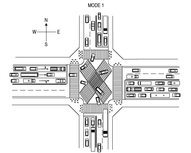
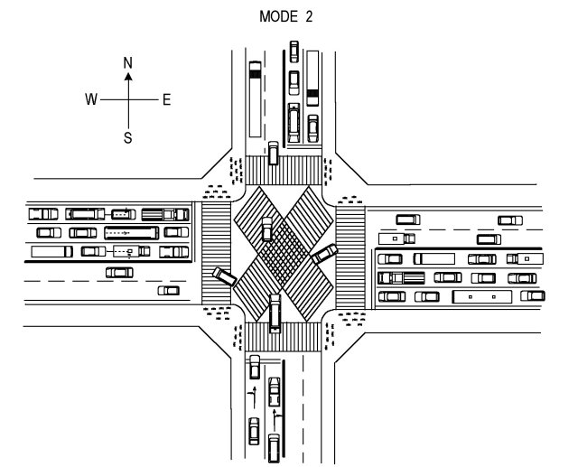
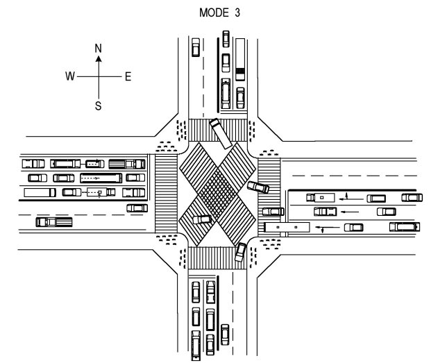
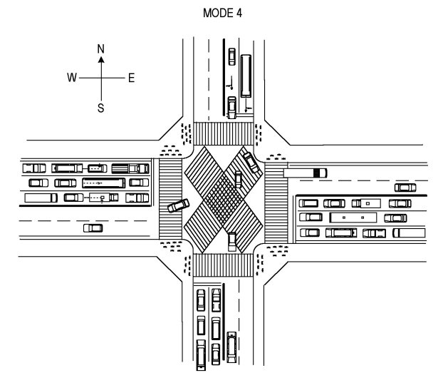
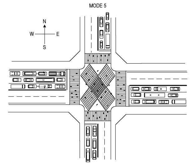
The Modes 1-5 are changed over
according to such a time schedule as shown hereinunder:
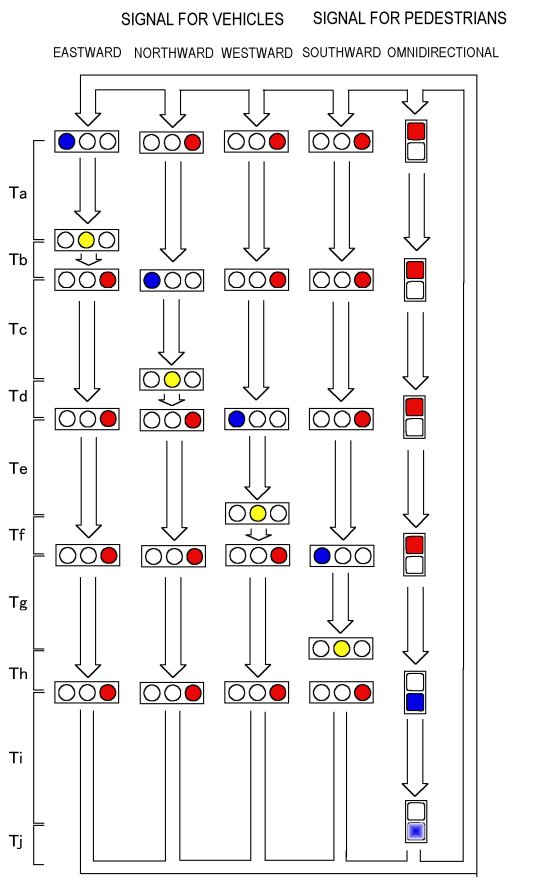
When the above Modes 1-4 are circulated in said order, the vehicle traversing the intersection last in a mode will be apart more from the vehicle starting to traverse the intersection by the green signal of the next mode than in any other mode circulation order.
An example of the time schedule is such as shown hereinunder:
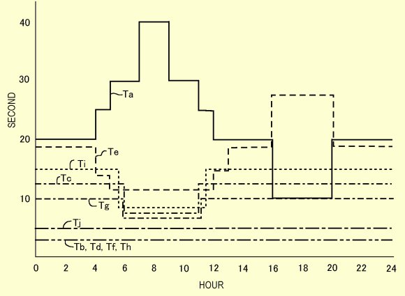
The hardware of the existing signal system can be used as it is.
Further, the frequent collision
accident between the right-turning vehicle and the opposing straight forwarding
vehicle will no longer happen.
Patent Claims
Claim 1
An intersection signal system for an intersection
where first and second roads each including vehicle drive lanes in opposite
directions intersect with one another, comprising
a first signal mode to make a signal light
for one of the vehicle drive lanes of the first road green while making
signal lights for all other vehicle drive lanes red and preventing all
traversing of the intersection by pedestrians,
a second signal mode to make a signal light
for another of the vehicle drive lanes of the first road green while making
signal lights for all other vehicle drive lanes red and preventing all
traversing of the intersection by pedestrians,
a third signal mode to make a signal light
for one of the vehicle drive lanes of the second road green while making
signal lights for all other vehicle drive lanes red and preventing all
traversing of the intersection by pedestrians, and
a fourth signal mode to make a signal light
for another of the vehicle drive lanes of the second road green while making
signal lights for all other vehicle drive lanes red and preventing all
traversing of the intersection by pedestrians,
wherein the above four signal modes are changed
over such that the vehicle drive lane of the green signal is circulated
anti-clockwise as viewed from above of the intersection, provided that
the first and second roads are to be kept to the left.
Claim 2
An intersection signal system according to
claim 1, further comprising a fifth signal mode as a mode for the circulation
to make the signal lights for all vehicle drive lanes red while allowing
pedestrians to traverse the intersection freely.
Claim 3
An intersection signal system according to
claim 1 or 2, wherein a period of execution of each of the signal modes
to be circulated is individually set according to at least one of the days
in a week and the times in a day.
Return to the top
Rotatable laundry pole
Herein proposed is a rotatable laundry pole
adapted to be able to dry a large amount of laundry in a short time at
a relatively narrow space such as a room or a porch of the apartment house.
The feature is in that a plurality of poles
rotate each along a perpendicular plane so as to be displaced relative
to one another, so that even when the laundry is in a high density in a
small space, the air around each piece is ventilated so as to expedite
drying out.
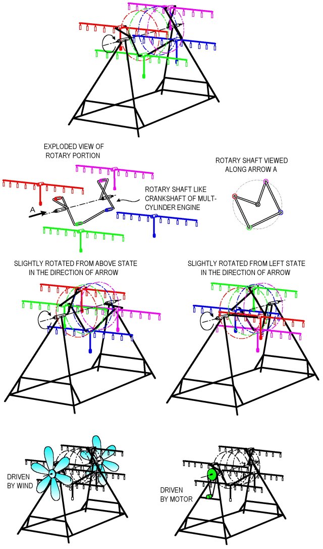
Patent Claims
Claim 1
A rotatable laundry pole comprising a support frame, first and second bearings supported by the support frame to align along a main rotational axis and spaced from one another therealong, and a rotary frame rotatable relative to the support frame around the main rotational axis in a space between the first and second bearings with a first end portion thereof being rotatably supported by the first bearing while another end portion thereof is rotatably supported by the second bearing,
wherein the rotary frame includes a plurality
of subbearings successively arranged in the direction of the main rotational
axis from the first end portion toward the second end portion as shifted
perpendicularly relative to the main rotational axis, intermediate connecting
members each connecting inner members of adjacent ones of the subbearings
with one another, a first end connecting member connecting an inner member
of one of the subbearings located adjacent to the first end portion of
the rotary frame with the firsrt end portion, a second end connecting member
connecting an inner member of one of the subbearings located adjacent to
the second end portion of the rotary frame with the second end portion,
and a plurality of laundry suspending pole members each supported by an
outer member of each of the subbearinds to extend perpendicularly relative
to the main rotational axis, the laundry suspending pole members each being
provided with a weight rod member extending from a portion thereof supported
by the subbearing downwardly so as to energize the laundry suspending pole
member in a horizontal posture.
Claim 2
A rotatable laundry pole according to claim
1, wherein the plurality of subbearings are angularly equally spaced around
the main rotational axis as viewed in the direction of extension of the
main rotational axis.
Claim 3
A rotatable laundry pole according to claim
1 or 2, wherein the laundry suspending pole members are each provided with
laundry clips for suspending laundry.
Claim 4
A rotatable laundry pole according to any
one of claims 1-3, wherein a wind turbine is mounted to the rotary frame
to generate a moment to rotate the rotary frame around the main rotational
axis by a wind.
Claim 5
A rotatable laudry pole according to any
one of claims 1-4, wherein an electric driving means is provided to rotate
the rotary frame around the main rotational axis.
Return to the top
Emergency ladder for high buildings
The high buildings are equipped with the
emergency stairs prepared for the state of emergency like the fire and
others, and further the emergency hatches at the corners of the porches
when the high buildings are for living purpose. However, even when
the emergency stairs and hatches are provided, it could happen that those
equipments can not be approached according to the location of the fire
or the direction of wind relative to the fire. In such a situation,
the last place definitely left for escape is a spot of an open space like
the porch remotest from the fire or the smoke. If there is an emergency
ladder in hand at that time, one can descend to the downfloor. However,
it would be only one floor or two at the most that one can descend by such
a handy emergency ladder as can be carried by hand in running along the
porch. Nevertheless, even when one could descend one or two floors
in the high building, it would be probable that the windows of the lower
floor are all locked. There would be no guarantee that the lower
floor is safer than the upper floor. Therefore, such an emergency
ladder would be almost useless for the high buildings.
Herein proposed is an emergency ladder which
can be easily carried by hand in running along the porch and still allows
one to descend any number of floors. It should however be noted that,
although it allows one to descend any number of floors, since it is of
such a light construction as can be carried by hand, it will require a
substantial courage for one to descend by it over the porches of the high
buildings. Nevertheless, there is a saying that the drowning grasps
even a straw. In the verge of life or death even the emergency ladder
of the light construction will be useful to help the desperate refugee.
Further, it is expected that one will be soon trained while desperately
trying. First of all, the probability of each man or woman to meet
with such a scene is extremely low, but still it is not zero as long as
he or she lives in the high apartment house. If the final lifeline
is at hand, one will feel a relief.
In view of the above the emergency ladder
herein proposed is designed to take a balance between the probability of
actual use and the cost. If this preparation ends in vain, it is
a better high luck. The expense lost thereby is very small.
The point is in that the ladder is equipped
with means for latching to the handrail or the like of the porch by opening/closing
of hooks at opposite ends thereof in such a manner that the hooks can be
opened directly by hand and also can be opened by a remote control at the
opposite end of the ladder. In operation, the ladder is first mounted
to the handrail or the like of the porch at one end thereof and is hung
down. Then the refugee decends along the ladder to the porch of the
lower floor. Then the lower end of the ladder is first mounted to
the handrail or the like of the lower floor. Thereafter, the mounting
of the upper end of the ladder to the handrail or the like of the upper
floor is released by opening the hooks of the upper end by the remote control
from the lower floor. Then the ladder will fall so as to hang down
from the present lower floor toward the next lower floor. By the
repetition of such operations one can descend any number of floors.
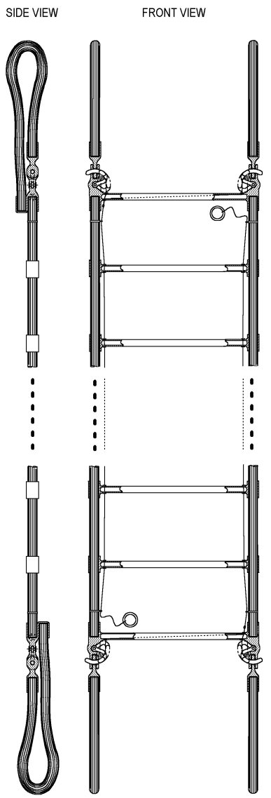
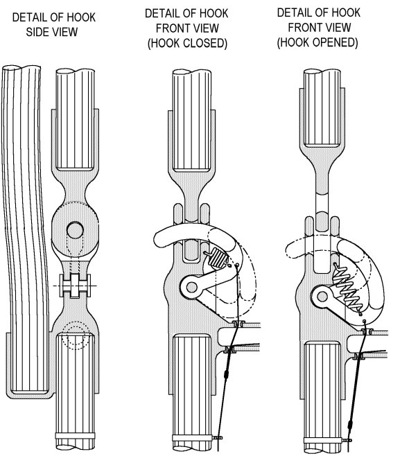
Patent Claims
Claim 1
An emergency ladder comprising a ladder portion
of a length corresponding the height of one or more floors of high buildings,
and mounting means for detachably mounting each of opposite ends of the
ladder portion to a rail or the like of the high buildings, the mounting
means each being adapted to be dissoluble of the mounting to the rail or
the like at the positions of both of the opposite ends, whereby the ladder
portin is mounted to the rail or the like of a floor at one end thereof
by the mounting means of the one end to be hung down toward another end
thereof so that one can descend from the floor to a lower floor along the
ladder portion, and then the mounting means at the one end is dissolved
from the lower floor by a remote control.
Claim 2
An emergency ladder according to claim 1, wherein the ladder portion is made of a pair of ropes and a plurality of crossbars bridged between the pair of ropes.
Claim 3
An emergency ladder according to claim 1
or 2, wherein each of the mounting means includes snips of ropes each connected
at one end thereof to one end of the ladder portion to extend therefrom
to be wrapped around the rail or the like, and a fastening means for detachably
fastening another end of the snip of rope to the one end of the ladder
portion.
Claim 4
An emergency ladder according to claim 3,
wherein each of the fastening means includes a hook hole formed at one
end of the ladder portion, a hook hole formed at the other end of the snip
of rope, a hook for insertion into an overlap of the hook hole at the one
end of the ladder portion and the hook hole at the other end of the snip
of rope, a spring for energizing the hook to a position inserted into the
overlap of the hook holes, and a string to be pulled for removing the hook
out of the overlap of the hook holes against the elasticity of the spring.
Claim 5
An emergency ladder according to claim 4, wherein the hook is a rotational hook to rotate between a position inserted into the overlap of the hook holes and a position removed out of the overlap of the hook holes.
Claim 6
An emergency ladder according to any one
of claims 1-5, wherein the mounting means are provided as a pair at each
of the opposite ends of the ladder portion.
Return to the top
External camera detachably mountable to tablet
It is now getting even more popular to do
a dialogue with tablets over the internet. However, since the eye
hole of the camera built in the tablet to shoot the face of the speaker
is opened at the edging frame of the tablet, the eyes of the companion
appearing in the window of the tablet are cast downward, upward or sideward
according to the posture of the companion's tablet, without straightly
facing this side, compelling a dialogue not to make eye contact. In
view of such an inconvenience herein is proposed an external camera which
can be detachably mounted to the tablet only when it is used for a dialogue
so as to locate the eye hole of the camera at the center of the window
so that the dialogue is made with both companions looking straightly at
each other's eyes.
Return to the top
The legs of dinosaurs are too thin.
(Appeared in "Patent", Apr. 1991, Journal of Japan Patent Attorneys
Association
The other day I saw the complete skeletons
of the tyrannosaur and other several dinosaurs at a Great Dinosaurs Exhibition
sponsored by Kaguken and TBS and was surprised by that their legs are awfully
thin and feeble.
The complete skeleton of the tyrannosaur
well known as the strongest carnivorous dinosaur on earth was the highlight
of the exhibition. Its main skeleton extended over 14 to 15 meters
from a huge egg-shaped cranial bone appearing fully over one meter along
a major axis down to a tail bone like a fallen tree by way of widely holding
ribs. However, the two legs which supported the central portion of
the magnificent main skeleton were awfully thin, and still further, they
were normally kneeling in a half-sitting posture. There was a notice that
this dinosaur is guessed to have weighed 6 tons.
The African elephant, the present heaviest
land animal, stands with four legs which are all postured perpendicularly
like logs elected with each rectangular end face being pressed against
the ground surface, so as to be easily able to support the heavy weight
of the body without applying a bending load thereto. However, the
tyrannosaur stood by two legs which were kneeling in a half-sitting posture
as described above. Further, there was not seen any pelvis-like bone
at a portion where the legs were connected with the main skeleton. Still
further, the tips of the legs were each branched into three nails all of
which were inclined about 30o downward relative to the ground surface to be in touch therewith only
at a small tip area. Judging from these facts, it is guessed that
the tyrannosaur in question was tip-toeing on the ground in a half-sitting
posture while supporting the weight of the body of 6 tons with two kneeling
legs.
Although it is afraid to be discourteous to compare
with tyrannosaur, the Sumou-wrestler Konishiki is thought of as an example
of creature who supports a huge body by two legs. Since he is a specially
trained professional wrestler, the movement of his body at the critical
moment is much quicker than that of an ordinary person in spite of the
huge body of 240 kg. However, after a breath he is everywhere producing
an atmosphere that the present weight is beyond the bearable limit. However,
the tyrannosaur was 25 times of Konishiki in the weight. And the
tyrannosaur should also have been moving its body fairly quickly in chasing
the prey which ran away.
In the Great Dinosaurs Exhibition there were
also shown the complete skeletons of huge dinosaurs standing with four
legs. The legs of those dinosaurs were also kneeling and tip-toeing
with the tip ends being branched into the nails, appearing to be suited
for a hop-skipping walk.
It is a primary matter in the strength of
materials that the tensile strength and the compressive strength, both
being the basic strength of the material, are proportional to the cross-sectional
area of the material, and are therefore proportional to square (2nd power)
of the so-called magnitude or size, or more precisely one dimensional measurement.
In contrast, the weight of the material is proportional to cube (3rd
power) of the one dimensional measurement. Therefore, for those who
must support their own weight by themselves like the alive animals and
the alive plants, the severity of weight loaded at each section of the
body increases with acceleration as the size increases. That is,
when the shape of the body is the same, the stress at each section of the
body increases by 2 times as the size increases by 2 times, the stress
increases by 3 times as the size increases by 3 times, and so on. Therefore,
the bones and the muscles of the King-kong of the height of 20 m must be
of 10 times high quality as compared with those of the gorilla of the height
of 2 m. Here should naturally be the limit for the living things
to be able to grow phisycally.
In the Great Dinosaurs Exhibition there was
a model of the tyrannosaur made as guessed from the skeleton and also an
illustration imagined to show how it was prowling with big legs each being
certainly like a lump of muscle. However, the muscle is a means mostly
to generate a tensile force, and the weight of the upper body imposed onto
the legs must be finally supported by the bones of the legs.
Under the present gravitational acceleration
of 9.80 m/sec2 on the ground surface of the earth would'nt it be only up to such as 240
kg to which Konishiki is weighing that an animal standing with two legs
can grow physically, since if it grows more to weigh, the movability of
the body is damaged, and not affordable particularly for the wild carnivorous
animal who must catch the prey which runs away?
Then why could the tyrannosaur grow up to
6 tons by standing with two legs? It was because the gravitational
acceleration on the ground surface of the earth had been much less than
the current value before 65 million years ago, so I surmise, and it is
guessed that the gravitational acceleration has suddenly increased to the
current value at a time of 65 million years ago so that not only the huge
dinosaurs like the tyrannosaur but also even middle to small reptiles and
other animals who had grown up to the light tip-toeing posture under the
small gravitational acceleration have died out in an instant as unbearable
of their own weight, while the huge plants like the ancient cedar have
gradually collapsed.
The sudden increase of the gravitational
acceleration is due to a sudden deceleration of the rotational speed of
the earth, though this is all a hypothesis.
At present the earth is making one rotation
by 24 hours. Since the diameter of the earth is 6380 km at the equator,
and as the centrifugal acceleration generated by a rotation of radius r
and angular velocity ω is rω2, the centrifugal acceleration currently acting to the objects located
at the equator is 0.0337 m/sec2. Since the gravitational acceleration on the ground surface of the
earth is about 9.807 m/sec2 though slightly different according to the latitude, a gravitational acceleration
such as 9.841 m/sec2 is acting as the universal gravitation due to the mass constructing the
earth.
Now, when it is assumed that the earth was making one rotation by 2 hours before 65 million years ago, and also that the earth was in the same shape as it is at present for the sake of simplicity though it would have been in a relatively flattened shape and presenting a larger diameter than at present at the equator when it rotated quicker since the earth contains the magma and gases so as to be slightly compressive and soft, then disregarding such a deformation of the earth, the centrifugal acceleration at the equator was 4.860 m/sec2, and therefore the gravitational acceleration appearing here would have
been 4.981 m/sec2. This means that the weight of the things is 50.1% of that at present. Conversely,
if the tyrannosaur was feeling his weight like 1.5 tons that is one fourth
of 6 tons to be felt at present, the earth was making one rotation by 1
hour, 37 minutes and 18 seconds.
Someone might criticize as it should be impossible
that this huge earth makes one rotation by such a short time as one hour
and half, but the earth is a high speed object rushing a distance such
as 73800 times of its diameter per year, or 202 times of its diameter per
day. It should be a matter of cinch for the earth to make one rotation
by one hour and half. By the way, when the rotational speed is in
such order, the gravitational acceleration to appear on the ground surface
varies much according to such a difference as one minute for one rotation,
that is, when the time of one rotation is 1 hour, 34 minutes and 14 seconds,
the weight of things to appear is reduced to 1/5, when such time is 1 hour,
32 minutes and 20 seconds, the weight of things to appear is reduced to
1/6, and when such time is 1 hour, 23 minutes and 19 seconds, the weight
of things to appear is reduced to zero.
Then why has the rotational speed of the
earth fallen suddenly so much as to be less than one tenth at a time of
65 million years ago? Here does the water planet according to the
hypothesis by Mr. Takahashi ("Incandescent Ice Planet" by Minoru
Takahashi, 1975, Hara Bookstore) wear a really high authenticity.
According to the hypothesis by Mr. Takahashi
there should be such a planet in our solar system that is of the same size
as the earth having a central core of a diameter half as much as the outer
diameter and a thick water layer holding the core and circulating around
the sun in a cycle of about 3000 years along an extremely elongated elliptical
orbit which traverses the orbit of the earth. This water planet collided
with the earth in the past, and splashed a large amount of water to the
earth at its latest approach to the earth, remaining in the memory of the
mankind as the Flood of Noah. The major axis of the abovementioned
extremely elongated elliptical orbit is about 30 billions km long so that
the water planet is apart from the earth so much as ten times of the orbit
radius 6 billions km of the Pluto when it is located at its aphelion that
it can not be seen even by the 200 inches reflecting telescope of the Mountain
Paloma, according to Mr. Takahashi.
Mr. Takahashi begins the story from the generation
of the present solar system and guesses the existance of the abovementioned
planet highly theoretically with verifications of many objective matters.
This planet is of the same size as the earth as mentioned above,
is made of water down to the depth as much as a half of its radius from
the surface, moves in the direction to accord with the equator of the earth
at a speed of 30 km per second relative to the earth when it approaches
the earth, and is capable of contacting with the earth in the direction
to accelerate or decelerate the rotation of the earth according to a slight
difference in the time of encountering with the earth. If this water
planet had collided with the earth with the thick water layer at a side
of the earth to decelerate the rotation of the earth, the earth rotating
at such a speed as to make one rotation in one hour and a little more would
have readily been decelerated so as to rotate at the present speed.
Since the earth rotating at a speed of one
rotation per one hour and half would present a circumferential speed such
as 7.423 km/sec at the equator, it is just suited to be decelerated by
the water planet of a relative speed such as 30 km/sec. If the earth
has contacted with the water planet so deeply as to traverse the full depth
of its water layer, the time to lapse for the contact to end from its start
is approximately 280 seconds. If the earth was uniformly decelerated
in the meantime from 1 rotation/1.5 hour to 1 rotation/24 hours, the accelerating
rate of the deceleration is 24.6 m/sec2, that is, 2.5 times of the current gravitational acceleration (G) on the
ground surface of the earth. One time the dinosaurs were suddenly
pulled over the ground surface by the force of 2.5G haphazardly for nearly
5 minutes, and when it finally ended, they could not stand up because of
their own weight to a great misery. Such a scene is however those
met in the North American area where the complete skeletons of dinosaurs
were abundantly digged out. At that time the area located diametrically
opposite thereto, i.e. the Middle East and African area which were deeply
soaked in the water layer of the water planet were no longer of any living
things as covered with an expansive dune contaminated with crude oil .....,
though this is what Mr. Takahashi has already suggested.
Even the rotation of the earth at the speed
of one rotation per one hour and a little more might have been obtained
by an acceleration at a preceding collision with the water planet . The
rotational speeds of the brother planets in our solar system are such that
those of the Mercury and Venus are 59 days and 245 days, respectively,
that of the Mars is 1.03 day, those of the Jupter, Saturn and Uranus are
0.41 day, 0.43 day and 0.45 day, respectively, that of the Neptune is 0.58
day, and that of the Pluto is 6.39 days. By analogy with those of
the brother planets the rotation by one hour and a little more would be
too fast to be original.
Indeed, according to the explanations of
the process of generation of the current solar system and the theoretical
inferences by Mr. Takahashi it is almost improbable that hydrogen and oxygen
encouter with each other on the earth to form water, but the water on the
earth was given from the water planet which gathered oxygen at a position
closer to the sun and hydrogen at a position far remote from the sun in
the circulaton along the abovementioned elongated elliptical orbit in the
cooling process after the supernova explosion of the ancient sun, thereby
forming the water before the oxygen and the hydrogen combine with other
elements. This is highly agreeable in view of the fact that the brother
planets genereted via the same process as the earth have almost no water.
It is guessed that the earth was first given with water by a collision
with the water planet and accelerated at that time or by a later collision,
so as to allow the creatures generated by the existance of water to grow
up to the huge dinosaurs, and then decelerated by a further collision with
the water planet to be in the present state. The high mountains and
the deep seas which appear to be particular only to the earth among the
brother planets are guessed to have been formed when an extensive contraction
has occurred in the ground surface layer due to the reduction of the centrifugal
acceleration caused by the deceleration of the rotation of the earth. It
is said that the age of the current solar system is 15 billion years. Therefore,
the abovementioned water planet has traversed the orbit of the earth nearly
5 million times.
In the end, it is suggested that the significance
of the gravitational acceleration is once again appreciated. We are
living in the field of the gravitational acceleration of 9.80 m/sec2and are used to the movement of the articles based upon the gravitational
force acting under such a gravitational acceleration and the inertial force.
Therefore, we felt strange when we saw the astronaut who landed on
the moon for the first time as the mankind to walk in a hop-skipping manner
on the moon surface by deeply kneeling his legs. However, the walking
movement which occurs in the walking creatures when the ratio of the gravitational
force to the inertial force acting to the mass is low is such a hop-skipping
walk performed by kneeling the legs deeply. The skeletons of the
tyrannosaur and other dinosaurs were seen to be exactly suited to such
a lively hop-skipping walk. (from "Patent" Apr. 1991, Journal of Japan Patent Attorneys Association)
Verification 1: There is a well known view that the extinction of the dinosaurs
is due to a cold climate caused by the fall of a meteor, but this will
be unable to explain why the crocodiles or alligators, lizards, snakes,
turtles or tortoises and others belonging to the same cold blood reptile
but in the creeping style have survived.
Verification 2: It is shown by the whales that the animals can grow gigantically
when released from the gravitational force.
Verification 3: The surface portion of the earth is formed of an assembly
of plates such as the Pacific Ocean Plate, North American Plate, Philipino
Sea Plate, Eurasian Plate, African Plate, etc. contiguous to each other
and moving to deepen the mutual overlapping at the joining regions to generate
occasionally the earthquakes and the tsunamis. This is guessed to
due to that a ball like solidified shell formed by the cooling of the surface
portion of the earth in the age of the quick rotation was broken into a
number of plates by the contraction due to the loss of the centrifugal
force caused by the deceleration of the rotation, and is still contracting
as a whole. If no such contraction force as due to the loss of the
centrifugal force caused by the deceleration of the rotation had acted,
the ball like solidified shell would have remained as it was, or even when
it had broken into the plates, there should occur no such movement as to
deepen the overlapping at the joining regions of the plates.
Verification 4: When the earth rotating at a speed of one rotation per
about one hour and half in the condition that the solidified ball shell
contains the magma therein was braked of its rotation at the shell to become
the present self rotating state, at that time the fluidal magma in the
shell should have rotated relative thereto in the clockwise rotational
direction as viewed from the side of Antarctic to the side of Arctic due
to its inertia as a reaction of the braking. It is considered that
by such a relative rotation of the magma in the shell a frictional sliding
has occurred between the shell and the magma around the earth rotation
axis so that a frictional electromotive force has magnetized the shell
symmetrically around the earth rotation axis to show an N pole at the Antarctic
and an S pole at the Arctic.
Verification 5: If the gravitational acceleration on the ground surface
had been so small in the era of the huge dinosaurs as to allow them to
grow so huge, the atmospheric air should have been correspondingly thin.
The volume of the lung estimated from the ribs of the tyrannosaur
and other dinosaurs is much larger than that of the current animals as
compared with the size of the body.
Return to the top